Solid-state laser element

a laser element and solid-state technology, applied in lasers, laser cooling arrangements, laser details, etc., can solve the problems of two-dimensional waveguide lasers with breaking limits, and two-dimensional waveguide lasers limited in high-power operation

Active Publication Date: 2011-11-29
MITSUBISHI ELECTRIC CORP
View PDF12 Cites 10 Cited by
  • Summary
  • Abstract
  • Description
  • Claims
  • Application Information

AI Technical Summary

Benefits of technology

[0010]A solid-state laser element according to the present invention is separated in a principal-surface width direction of the solid-state laser element by a groove extending in an optical axis direction within a laser medium, so that a laser propagation distance in the principal-surface width direction can be shortened, and a high-power laser can be output with a gain in a direction other than the optical axis direction suppressed.

Problems solved by technology

However, the two-dimensional waveguide laser has a breaking limit due to the high power density, so that the two-dimensional waveguide laser is limited in high power operation.
Furthermore, an output of an LD (Laser Diode) beam with a high beam quality in a two-dimensional direction connectable to a two-dimensional waveguide (in the same plane as the two-dimensional waveguide) is generally low, so that the two-dimensional waveguide laser is limited in high power operation.

Method used


Image

  • Solid-state laser element
  • Solid-state laser element
  • Solid-state laser element

Examples


embodiment (

Embodiment(s)

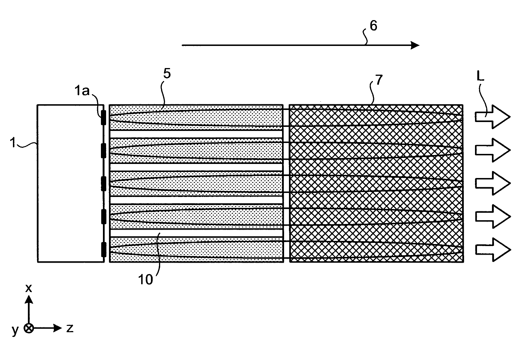
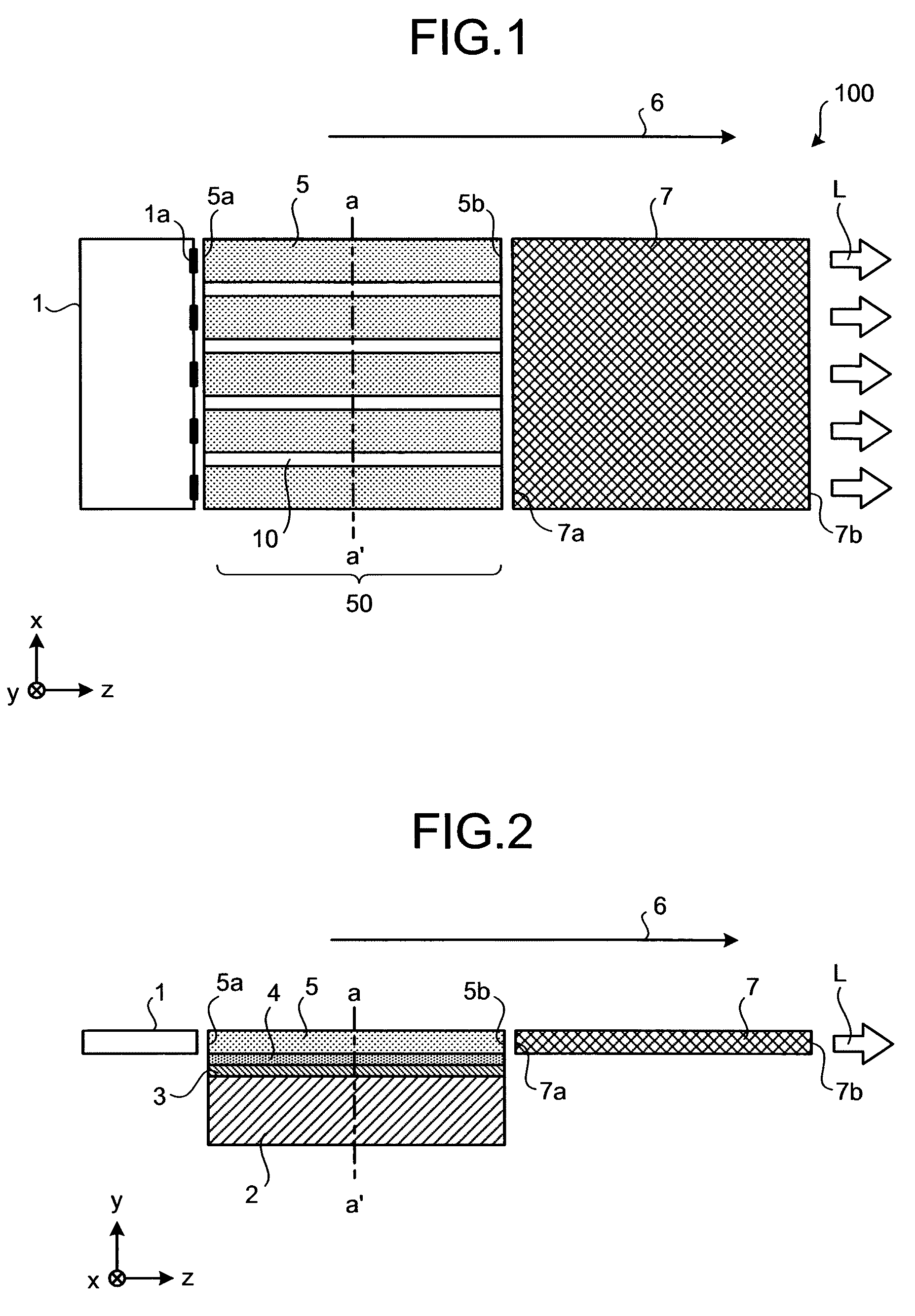
[0053]FIG. 1 is a top view illustrating a configuration of a wavelength conversion laser device according to an embodiment of the present invention, and FIG. 2 is a cross-sectional view of the configuration of the wavelength conversion laser device according to the embodiment of the present invention from a lateral view. Incidentally, in FIGS. 1 and 2, an optical axis representing a laser oscillation direction is denoted by an optic axis 6.

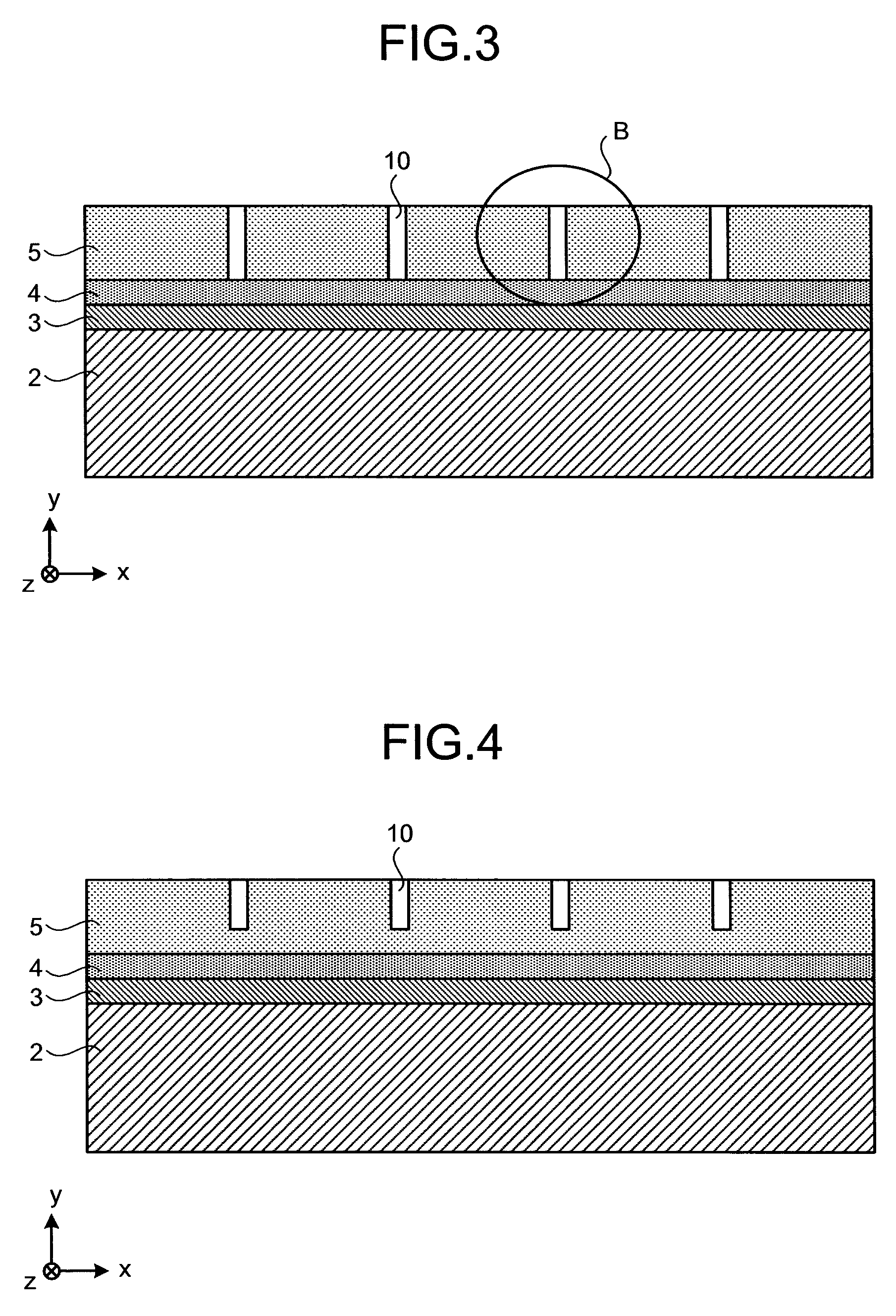
[0054]A planar waveguide type wavelength conversion laser device 100 is a laser system in which grooves (groove wall surfaces) are formed on a laser medium to suppress a parasitic oscillation and an extraction of energy due to amplification of a spontaneous emission light in a direction other than the direction of the laser beam axis (the optic axis 6). The wavelength conversion laser device 100 is used, for example, in the optical information processing field and the like, as a light source of a laser display device or an optical mem...


PUM


Abstract

To achieve a solid-state laser element capable of outputting a high-power laser, in a planar waveguide type solid-state laser element that causes a plurality of fundamental laser beams to oscillate in a direction of an optic axis within a flat plate-like laser medium, and forms a waveguide structure in a thickness direction of the laser medium, which is a direction perpendicular to a principal surface of the flat plate-like laser medium, the laser medium is separated in a principal-surface width direction of the laser medium, which is a direction perpendicular to the direction of the optic axis and the thickness direction of the laser medium, by a groove extending in the direction of the optic axis within the laser medium.

Description

TECHNICAL FIELD[0001]The present invention relates to a solid-state laser element that outputs a laser beam while oscillating the laser beam within a flat plate-like planar waveguide.BACKGROUND ART[0002]An apparatus that displays a color image, such as a printer or a projection television, requires, as a light source, light sources of three colors: red (R), green (G), and blue (B). In recent years, as these light sources, there has been developed a wavelength conversion laser device (a laser system) that sets laser beams in the 900 nm band, the 1 μm band, and the 1.3 μm band as fundamental laser beams, and converts a fundamental laser beam into a second harmonic (SHG: Second Harmonic Generation) with a nonlinear material. In the SHG, to achieve a high conversion efficiency of the conversion from the fundamental laser beam to the second harmonic laser beam, the wavelength conversion laser device is required to increase a power density of the fundamental laser beam on the nonlinear ma...

Claims


Application Information

Patent Timeline
Patent Type & Authority Patents(United States)
IPC IPC(8): H01S3/04
CPCH01S3/0632H01S3/0405H01S3/0625H01S3/09415H01S3/109H01S3/2383H01S2301/02
Inventor YAMAMOTO, SHUHEIYANAGISAWA, TAKAYUKIKOYATA, YASUHARUHIRANO, YOSHIHITO
Owner MITSUBISHI ELECTRIC CORP
Why Eureka
Try Eureka