Fuel injection stream parallel opposed multiple electrode spark gap for fuel injector

a fuel injector and fuel injection stream technology, applied in spark plugs, machines/engines, mechanical equipment, etc., can solve the problems of increasing the control volume pressure and closing of the needle valve, ethanol does not have suitable ignition properties, and the ignition delay is longer, so as to increase the ignition efficiency

Active Publication Date: 2011-12-06
BIG CAT ENERGY CORP
View PDF33 Cites 44 Cited by
  • Summary
  • Abstract
  • Description
  • Claims
  • Application Information

AI Technical Summary

Benefits of technology

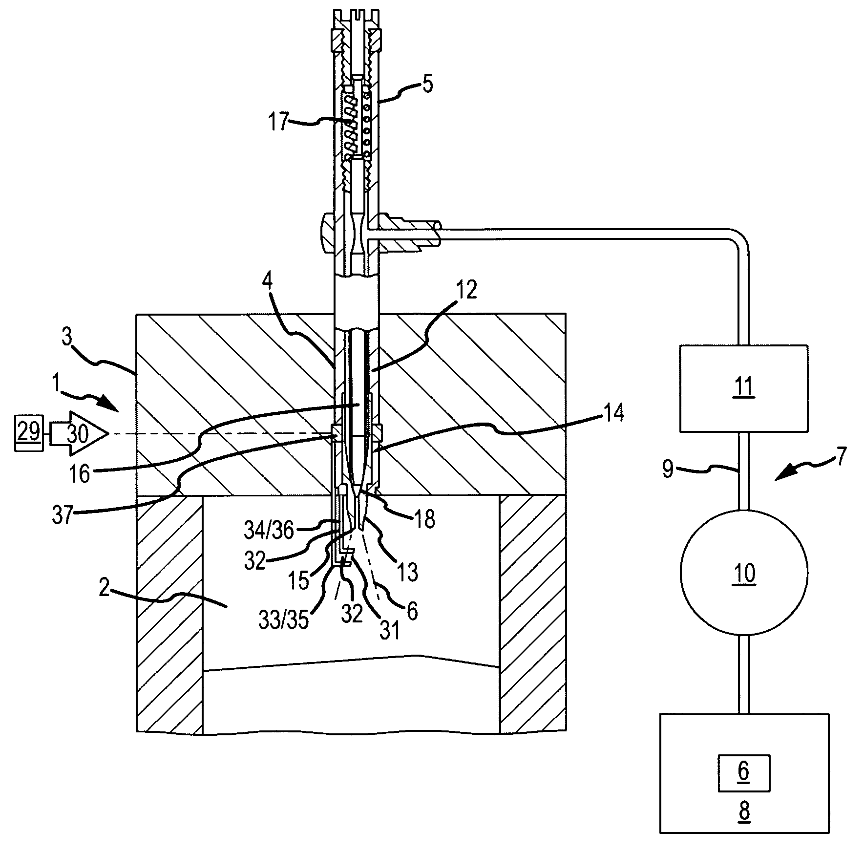
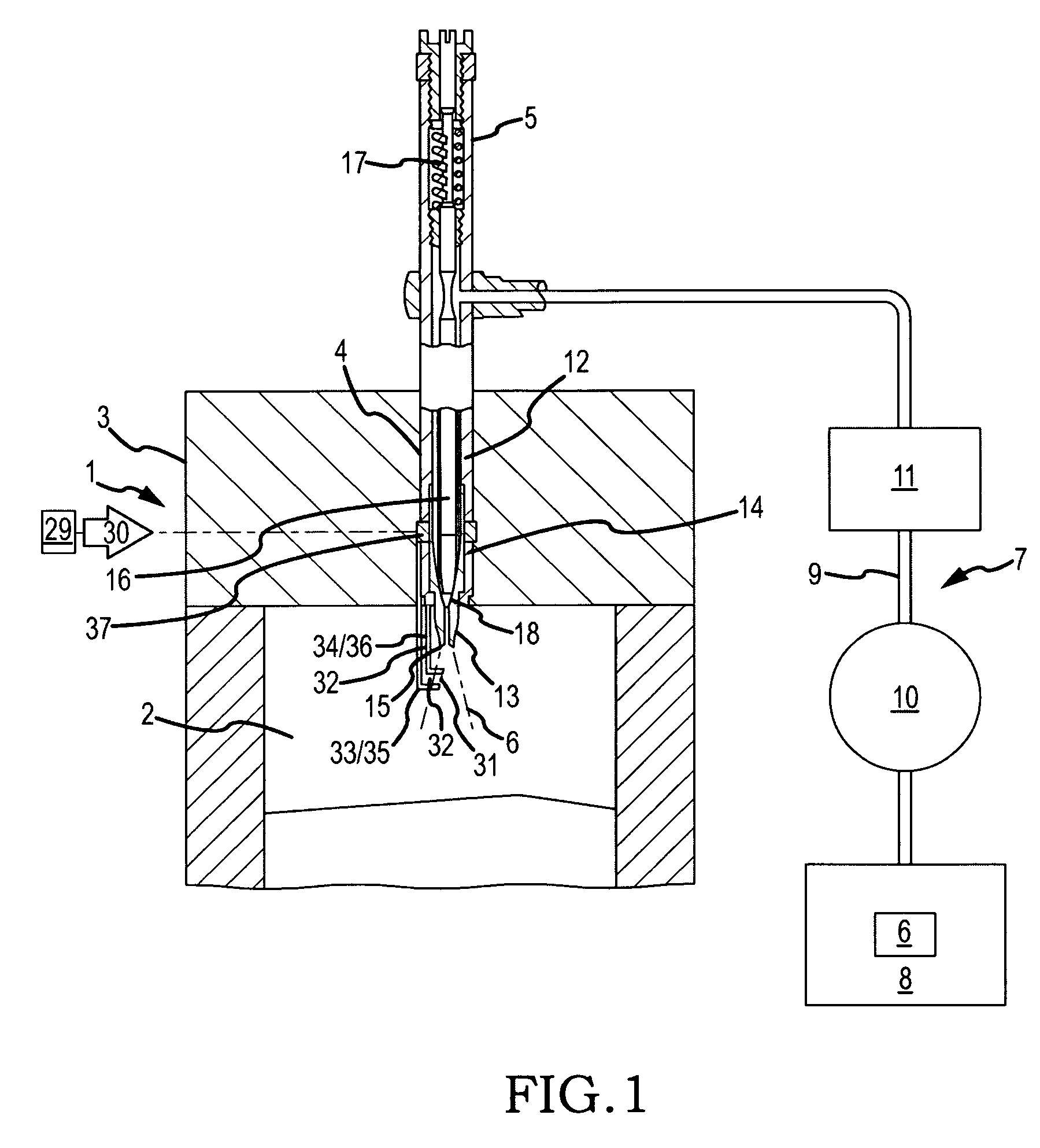
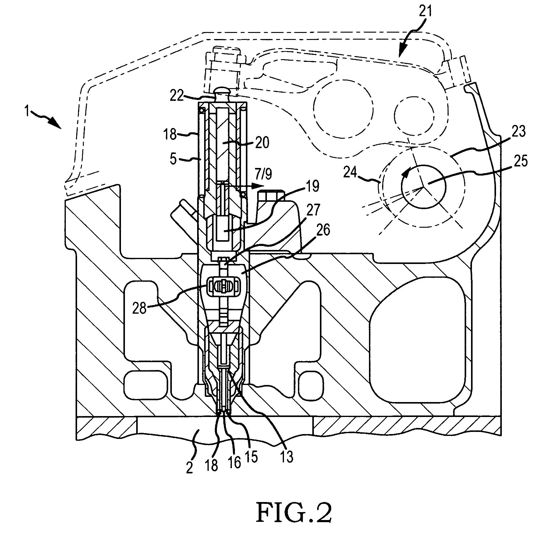
[0028]Accordingly, a broad object of the invention can be to provide a fuel injector which further includes at least one pair of conductors having a corresponding pair of conductor ends radially located and axially located in relation to an amount of fuel dispersed from the fuel injector nozzle to increase efficiency of ignition and fuel combustion upon discharge of an electrically current across the gap established between a first conductor end and a second conductor end.
[0029]Another broad object of the invention can be to provide a fuel injector which further includes at least one pair of conductors having a corresponding pair of conductor ends radially and axially located proximate a fuel dispersion boundary of a fuel dispersion pattern of an amount of fuel dispersed from the fuel injector nozzle to increase efficiency of ignition and fuel combustion upon discharge of an electrically current across the gap established between a first conductor end and a second conductor end.
[0030]Another broad object of the invention can be to provide a fuel injector which further includes at least one pair of conductors having a corresponding pair of conductor ends with the first of the pair of conductors and the second of the pair of conductors aligned radially about the longitudinal axis of the injector nozzle with the first of the pair of conductor ends disposed closer to the nozzle of the fuel injector than the second of the pair of conductor ends to increase efficiency of ignition and fuel combustion upon discharge of an electrically current across the gap established between a first conductor end and a second conductor end.
[0031]Another broad object of the invention can be to provide a fuel injector which further includes at least two pair of conductors having a corresponding at least two pair of conductor ends with the first of the pair of conductor ends disposed in substantially oppose relation radially about the longitudinal axis of the nozzle of the fuel injector, and in addition as to other embodiments, locating the first pair of conductor ends proximate the nozzle and the second pair of conductor ends distal from the nozzle, and in addition as to other embodiments, locating a first of each pair of conductor ends proximate the nozzle and a second of each pair of conductor ends distal from the nozzle, and in addition as to other embodiments, locating each conductor end proximate the fuel dispersion boundary of the fuel injection pattern of the amount of fuel dispersed from the nozzle of the fuel injector, each embodiment configured to increase efficiency of ignition and fuel combustion upon discharge of an electrically current across the gap established between a first conductor end and a second conductor end.

Problems solved by technology

Opening of the injection control valve causes a reduction in the fuel pressure in the control volume resulting in a pressure differential which forces the needle valve open, and closing of the injection control valve causes an increase in the control volume pressure and closing of the needle valve.
Unfortunately ethanol does not have suitable ignition properties under typical diesel conditions because the temperatures and pressures characteristic of the diesel engines causes a longer ignition delay while using ethanol.
However, as the concentration of bio-fuel is increased cold engine start may require additional engine cranking and cold engine operation may be substantially inferior to diesel fuel.
At some point, however, spark ignition comes too early and the pressure produced from combustion works against the piston (on the up stroke) more than it works with the piston (on the down stroke).
In newer vehicles, how much fuel to deliver to the fuel combustion cylinder and when to provide ignition spark is typically monitored by computers which use sensors to detect engine “ping” or “knock” and to reduce emissions; however, the amount of ignition control that can be achieved under a broad range of operating conditions may be insufficient to completely eliminate “ping” or “knock” under certain circumstances, for example when low octane fuel is used.
Also, the computer may be reacting to something that is already happening or has happened, and engine “ping” or “knock” has the potential to be harmful with relatively few occurrences.
Third, aviation remains the only transportation industry in the United States whose engine emissions are not yet regulated.
While turbine engine manufacturers have dedicated considerable resources to reduce engine emissions, the airline industry has experienced unprecedented growth and the aggregate pollution has increased dramatically.
Because existing technology may not allow sufficient ignition control to eliminate “ping” and “knock” under certain circumstances and aircraft engines may then experience increased wear similar to that experienced in automobile engines using lower octane fuels.
While aviation applications of bio-fuels are economically competitive with aviation fossil fuels, and are actually less expensive if the real cost of the fossil fuels is taken into account, the use of bio-fuels may be limited due to reduced performance of aviation engines under certain conditions as above-described and may require an ignition aid.

Method used


Image

  • Fuel injection stream parallel opposed multiple electrode spark gap for fuel injector
  • Fuel injection stream parallel opposed multiple electrode spark gap for fuel injector
  • Fuel injection stream parallel opposed multiple electrode spark gap for fuel injector

Examples


examples

[0067]Twenty seven ignition tests were performed each test consisting of a specific conductor configuration including, but not limited to, the above-described embodiments of the invention. As to each test of a specific conductor configuration, the pair of conductor ends were disposed in a fixed relation to the nozzle orifice of the fuel injector as fuel was emitted from the nozzle orifice with the fuel disperson pattern substantially the same between tests. Each test included approximately 43 trials each trial including a discharge (spark) between the pair of conductor ends with even polarity change. Each discharge and the resulting level of fuel ignition was video recorded. The interval between trials in each test was sufficient to allow recovery of the fuel dispersion pattern prior to the next discharge of the electrical current between the pair or multiple pairs of conductors. The video recordings were analyzed for fuel ignition and fuel ignition characteristics.

[0068]Configurati...


PUM


Abstract

Generally, a multiple electrode spark gap fuel injector and methods of utilizing a multiple electrode spark gap fuel injector for internal combustion engines. Specifically, at least one pair of electrodes having a corresponding pair of electrode ends radially located and axially located in relation to an amount of dispersed fuel to increase efficiency of fuel combustion.

Description

I. BACKGROUND[0001]Generally, a multiple electrode spark gap fuel injector and methods of utilizing a multiple electrode spark gap fuel injector for internal combustion engines. Specifically, at least one pair of electrodes having a corresponding pair of electrode ends radially located and axially located in relation to an amount of dispersed fuel to increase efficiency of fuel combustion.[0002]Fuel injectors convert fuel into a fine spray which is mixed with air in engine combustion chambers. The major advantage of the system is that the amount of fuel being mixed with air can be more precisely controlled and the mixture can be more evenly spread throughout the air coming into the engine. In combination with an electronic computer which monitors engine conditions and exhaust emissions, fuel injection can increase fuel efficiency and reduce pollution.[0003]Fuel injection was adapted for use in petrol-powered aircraft during World War II and was first used in a car in 1955 with the i...

Claims


Application Information

Patent Timeline
Patent Type & Authority Patents(United States)
IPC IPC(8): F02M57/06
CPCF02M57/06F02P13/00F02P15/08F02M57/023F02M61/20
Inventor EHRESMAN, THOMAS EMANUEL
Owner BIG CAT ENERGY CORP
Why Eureka
Try Eureka