Gradient elution electrophoresis

a technology of gradient elution and electrophoresis, which is applied in the direction of fluid pressure measurement, liquid/fluent solid measurement, peptide measurement, etc., can solve the problems of increasing the space required for implementing itp in a microfluidic, difficult to differentiate the continuous zone, and increasing the method of citp

Active Publication Date: 2011-12-20
GOVERNMENT OF THE UNITED STATES OF AMERICA AS REPRESENTED BY THE SEC OF COMMERCE THE NAT INST OF STANDARDS & TEHCNOLOGY
View PDF7 Cites 13 Cited by
  • Summary
  • Abstract
  • Description
  • Claims
  • Application Information

AI Technical Summary

Problems solved by technology

When using other on-line detectors, such as single response optical detection (e.g., fixed wavelength absorbance or fluorescence), differentiation of the continuous zones becomes difficult.
There are two primary disadvantages to the common method of performing cITP.
Second, long channels are required to produce high enrichment factors for dilute solutions or to produce high-resolution separations.
Both of these disadvantages increase the space required to implement ITP in a microfluidic chip format.
Although long separation channels can be fit into a small area on a microfluidic chip using a serpentine pattern, every turn in the path of the separation channel degrades the separation resolution.
Consequently, microchip ITP still generally gives lower resolution separations than can be achieved with conventional capillary-based ITP.
This has additional disadvantageous consequences in ITP, as the slowest analytes will have the lowest enrichment based on the Kohlrausch regulating function.
While eliminating electrical injection bias, hydrodynamic injections suffer from possible sample injection plug broadening due to the laminar flow profile induced by the pressure differential, ultimately leading to analyte zone broadening and a loss in separation efficiency.
Additionally, hydrodynamic injections are much more difficult to implement in a microfluidic format, either necessitating off-chip injection equipment or complicated fabrication procedures, as the gravity fed method of injection is not readily available.

Method used


Image

  • Gradient elution electrophoresis
  • Gradient elution electrophoresis
  • Gradient elution electrophoresis

Examples


Embodiment Construction

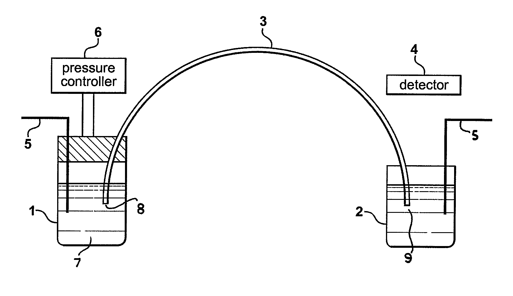
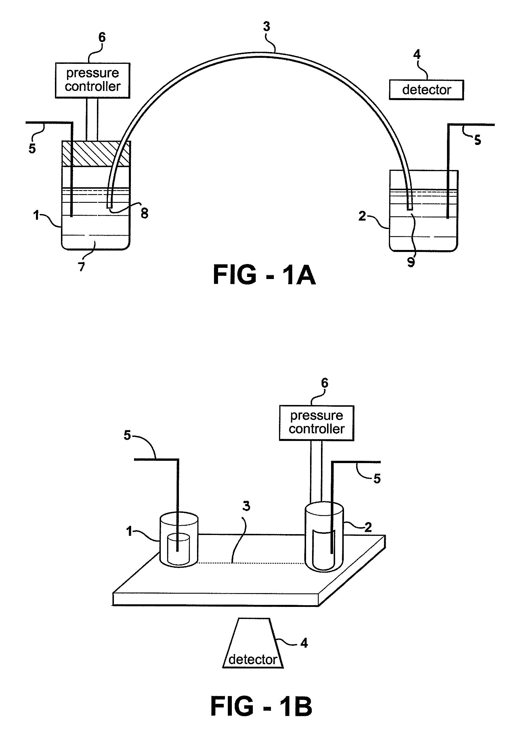
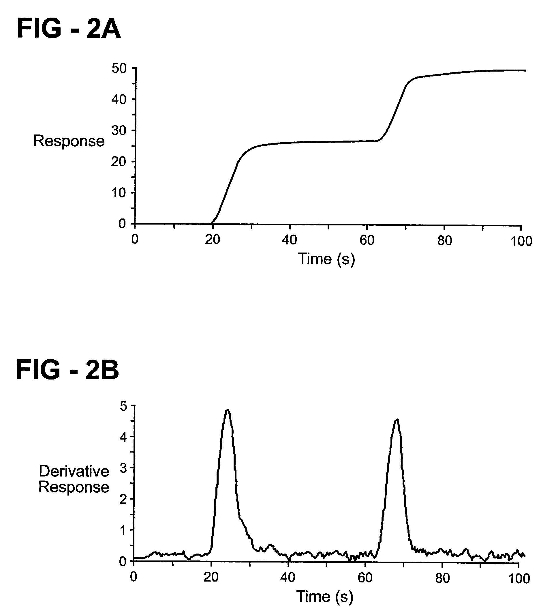
[0042]The present invention incorporates a process for coupling continuous sample introduction with a variable hydrodynamic bulk flow for electrophoretic separations in a capillary, microfluidic channel, or other separation column. By changing the bulk flow velocity over time during the separation, analytes are sequentially eluted onto the separation column from the sample where they can individually be detected as zone boundaries. The present invention further provides a method for the enrichment and separation of the constituents of a sample mixture, which enrichment method can be used in conjunction with the process for coupling continuous sample introduction with a variable hydrodynamic bulk flow for electrophoretic separations in a capillary, microfluidic channel, or other separation columns.

[0043]The method can be applied to a capillary or microfluidic system. In this regard FIG. 1a is a schematic drawing of a capillary system that can be used according to one embodiment of th...


PUM

PropertyMeasurementUnit
outer diameteraaaaaaaaaa
lengthaaaaaaaaaa

Abstract

A method for performing electrophoretic separation of ionic compounds which involves varying a bulk fluid flow though a separation path into which ionic species are continuously introduced and separated. The method can also include the introduction of a leading electrolyte into the separation path to form an ionic interface with the sample and an optional terminating electrolyte to enrich ionic species for higher detection resolution.

Description

TECHNICAL FIELD[0001]The present invention relates in general to electrophoretic separations, both in capillaries and in microfluidic channels, in order to preconcentrate, separate and / or purify compounds from a sample mixture. More particularly the present invention relates to the combination of electrophoresis in the presence of a variable hydrodynamic flow with continuous introduction of sample. Further the present invention relates to microfluidic devices for conducting trace analysis which have small total footprint areas.BACKGROUND ART[0002]Electrophoresis is a well known analytical method for separation of ionic compounds (analytes) in a sample mixture through use of an applied voltage. The voltage is applied to either end of a separation path (U-tube, gel, capillary, microfluidic channel, etc.), and the analytes are thereby caused to move along the separation path. The separation mechanism is based mainly on differences in analytes' size and charge, although other factors ca...

Claims


Application Information

Patent Timeline
Patent Type & Authority Patents(United States)
IPC IPC(8): G01N27/447
CPCB01D57/02G01N27/44769
Inventor ROSS, DAVID J.SHACKMAN, JONATHAN G.
Owner GOVERNMENT OF THE UNITED STATES OF AMERICA AS REPRESENTED BY THE SEC OF COMMERCE THE NAT INST OF STANDARDS & TEHCNOLOGY
Why Eureka
Try Eureka