Rolling apparatus

a technology of rolling bearings and rolling bearings, which is applied in the direction of heat treatment apparatus, furnaces, manufacturing tools, etc., can solve the problems of insufficient life, inability to provide sufficient effect, and harsh environment where the rolling bearing is used, so as to prevent an increase in tangential force, enhance indentation resistance and abrasion resistance, and enhance flaking resistance strength

Active Publication Date: 2012-01-03
NSK LTD
View PDF9 Cites 9 Cited by
  • Summary
  • Abstract
  • Description
  • Claims
  • Application Information

AI Technical Summary

Benefits of technology

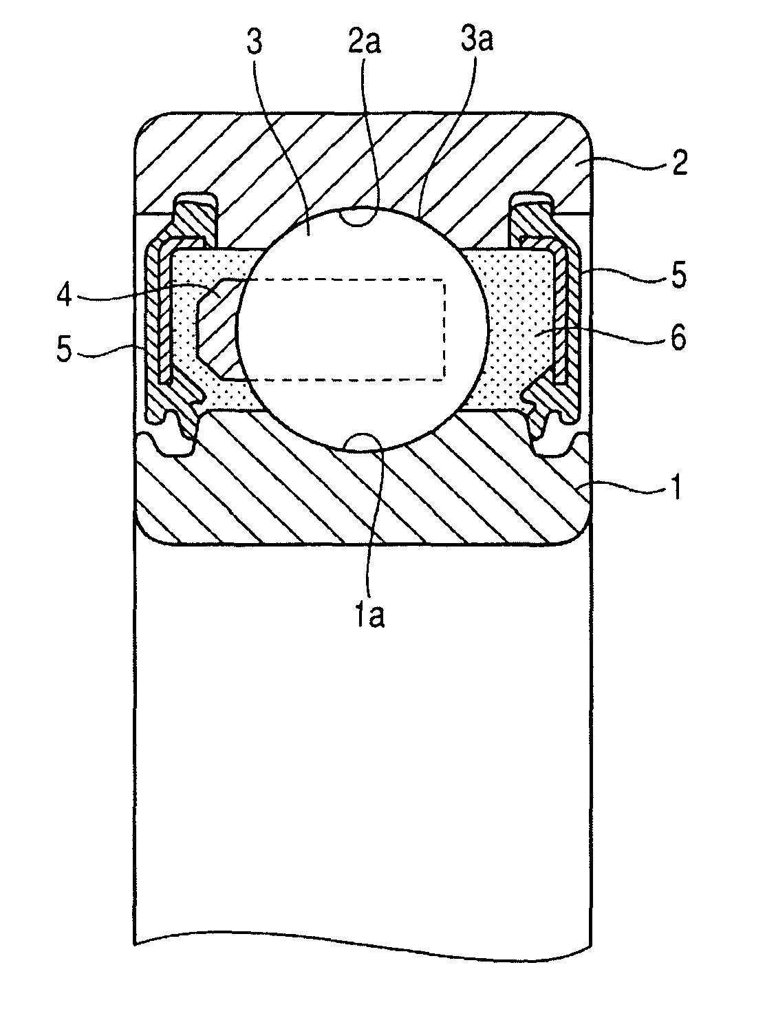
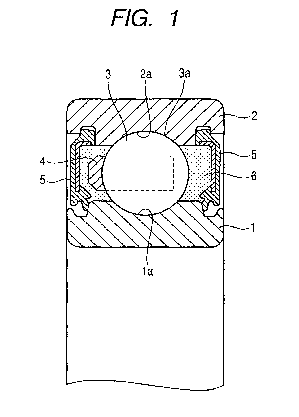
[0055]A rolling apparatus of the present invention enhances indentation resistance and abrasion resistance by defining the hardness of an internal member, the hardness of an external member, and the hardness of rolling elements which are achieved at a surface level and a specific depth and an area percentage of an Si.Mn-based nitride, thereby preventing an increase in tangential force between the rolling elements and the raceway ring during use of a bearing and enhancing flaking resistance strength.

Problems solved by technology

However, in an environment where a foreign substance is contaminated to lubricant or insufficient lubrication is achieved as result of diversification of an environment where a rolling bearing is used, it may be the case where the bearing steel will fail to provide sufficient life or where seizure will arise.
However, the environment where the rolling bearing is used has recently become harsh further, and there arises a case where a sufficient effect is not yielded by merely subjecting SUJ2 to carbonitriding.
Further, it has been well known that foreign substances, such as metal chips, shavings, burrs, dust resulting from abrasion, and the like, which are mixed in bearing lubricating oil inflict damage on a raceway ring or rolling elements of a rolling bearing, to thus significantly shorten the life of the rolling baring.

Method used


Image

  • Rolling apparatus
  • Rolling apparatus
  • Rolling apparatus

Examples


examples

[0145]Although the present invention will be further described hereunder by examples and comparative examples, the present invention is not limited to these examples.

[0146](First Test)

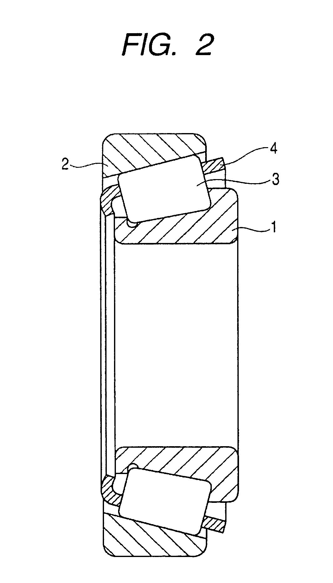
[0147]A life test was carried out in lubrication contaminated with foreign substances by using a conical roller bearing L44649 / 610 (the diameter of a rolling element d=5.44 mm) as a test bearing after excessive contact pressure of 4000 MPa was exerted on the bearing once. Test conditions are as follows:[0148]Test load: Fr=12 kN, Fa=3.5 kN[0149]Number of revolutions: 3000 min−1 [0150]Lubricating oil: VG68[0151]Hardness of foreign substance: HV870[0152]Size of foreign substance: 74 to 134 μm[0153]Amount of contaminated foreign substance: 0.1 g

[0154]High-carbon chromium bearing steel (SUJ2) was used for inner and outer rings of the test bearing, and the bearing was subjected to carbonitriding for 1 to 3 hours at 830 to 850° C. in an atmosphere consisting of an RX gas, an enriched gas, and an ammonium gas....


PUM

PropertyMeasurementUnit
sizeaaaaaaaaaa
areaaaaaaaaaaa
contact pressureaaaaaaaaaa

Abstract

A rolling apparatus including an external member having a raceway surface on an inner peripheral surface thereof, an internal member having a raceway surface on an outer peripheral surface thereof, and a plurality of rolling elements which are rotatably provided between the raceway surface of the external member and the raceway surface of the internal member. A surface of at least one of the internal member, the external member, and the rolling elements is subjected to carbonitriding or nitriding; an area percentage of a nitride containing Si and Mn is 1% or more and 20% or less; surface hardness is HV750 or more. When depth from the raceway surface or depth from a rolling surface of the rolling element is defined as Z and diameter of the rolling element is defined as d, hardness at Z=0.045 d is HV650 to 850, and hardness at Z=0.18 d is HV400 to 800.

Description

TECHNICAL FIELD[0001]The present invention relates to a rolling apparatus, such as a rolling bearing, a ball screw, a linear guide, and the like.BACKGROUND ART[0002]In a rolling bearing, such as a ball bearing, a cylindrical roller bearing, a conical roller bearing, a self-aligning roller bearing, a needle bearing, and the like, used in an environment involving harsh lubrication conditions as in; for instance, an automobile, construction machinery, agricultural machinery, an iron and steel fixture, and the like, there is a high probability of: foreign substances being introduced into lubricating oil; indentation arising in a raceway surface as a result of biting of the foreign substances; and early exfoliation starting from the indentation.[0003]A method proposed for solving the problem is to make an attempt to elongate flaking life by subjecting inner and outer rings and rolling elements to carburizing or carbonitriding, to thus precipitates a predetermined amount of retained auste...

Claims


Application Information

Patent Timeline
Patent Type & Authority Patents(United States)
IPC IPC(8): C23C8/32F16C33/32
CPCC21D1/06C21D9/40C22C38/02C22C38/04C22C38/18C23C8/26C23C8/32F16C33/32F16C33/34F16C33/62F16C33/64C21D1/10Y10S148/906C21D2211/001C21D2211/008F16C19/06F16C19/364F16C29/0647F16C2202/04Y02P10/25
Inventor UEDA, KOJIUEDA, TORUSENO, NAOYAMITAMURA, NOBUAKI
Owner NSK LTD
Why Eureka
Try Eureka