Fiber optic splice

a fiber optic splicing and fiber optic technology, applied in the field of splicing optical fibers, can solve the problems of insufficient avionics applications for failure of standard fiber optic splicing technology, and difficulty in pulling and replacing complete runs of fiber cables within an aircraft, and achieve the effect of maximum signal strength

Active Publication Date: 2012-01-17
AMERICAN TELEPHONE & TELEGRAPH CO
View PDF10 Cites 11 Cited by
  • Summary
  • Abstract
  • Description
  • Claims
  • Application Information

AI Technical Summary

Benefits of technology

[0024]The method may further comprise the steps of rotating the fiber ends relative to each other before fixing the outer splice assembly to the fiber cable ends; measuring signal strength across the splice during the rotating; and performing the fixing at a relative rotational position of the fiber ends resulting in a maximum signal strength.

Problems solved by technology

As with standard wiring, it is very difficult to pull and replace complete runs of fiber cable within an aircraft.
Standard fiber optic splice technology, however, is not adequate for avionics applications.
The temperature range, mechanical forces, humidity variations and environmental conditions including salt, sand and smoke encountered in fighter jet operating conditions, cause standard fiber optic splices, such as those used in the standard telecommunications field, to fail.
The ABDR repair, on the other hand, must quickly get the aircraft flight worthy but may have lower performance and lifetime specifications.
A problem often encountered in the use of presently available fiber optic splicing techniques for ABDR is that the fibers to be spliced must be cleaved to a very precise length tolerance, and that the fiber ends must be perpendicular and smooth in preparation for splicing.
Those procedures present significant difficulties in an ABDR environment where working space is limited and time is of the essence.
Another difficulty with fiber optic splicing techniques presently available for avionics is that there is no real-time feedback to the operator regarding the actual alignment and positioning of the two cleaved fiber ends with respect to each other.
That results in inconsistent results in splice quality, as measured by transmission loss through the splice.
Such losses are not measurable until the splice is completed, and the entire splicing process must be repeated if the results are substandard.
Presently available techniques furthermore require the use of expensive custom-made tools, raising the per-splice overall cost.
Adhesives, however, are difficult to use under tight working conditions and have limited shelf life, requiring careful inventory control.
That situation may necessitate multiple splices on some cables.

Method used


Image

  • Fiber optic splice
  • Fiber optic splice
  • Fiber optic splice

Examples


Embodiment Construction

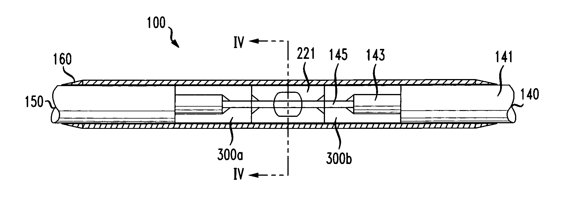
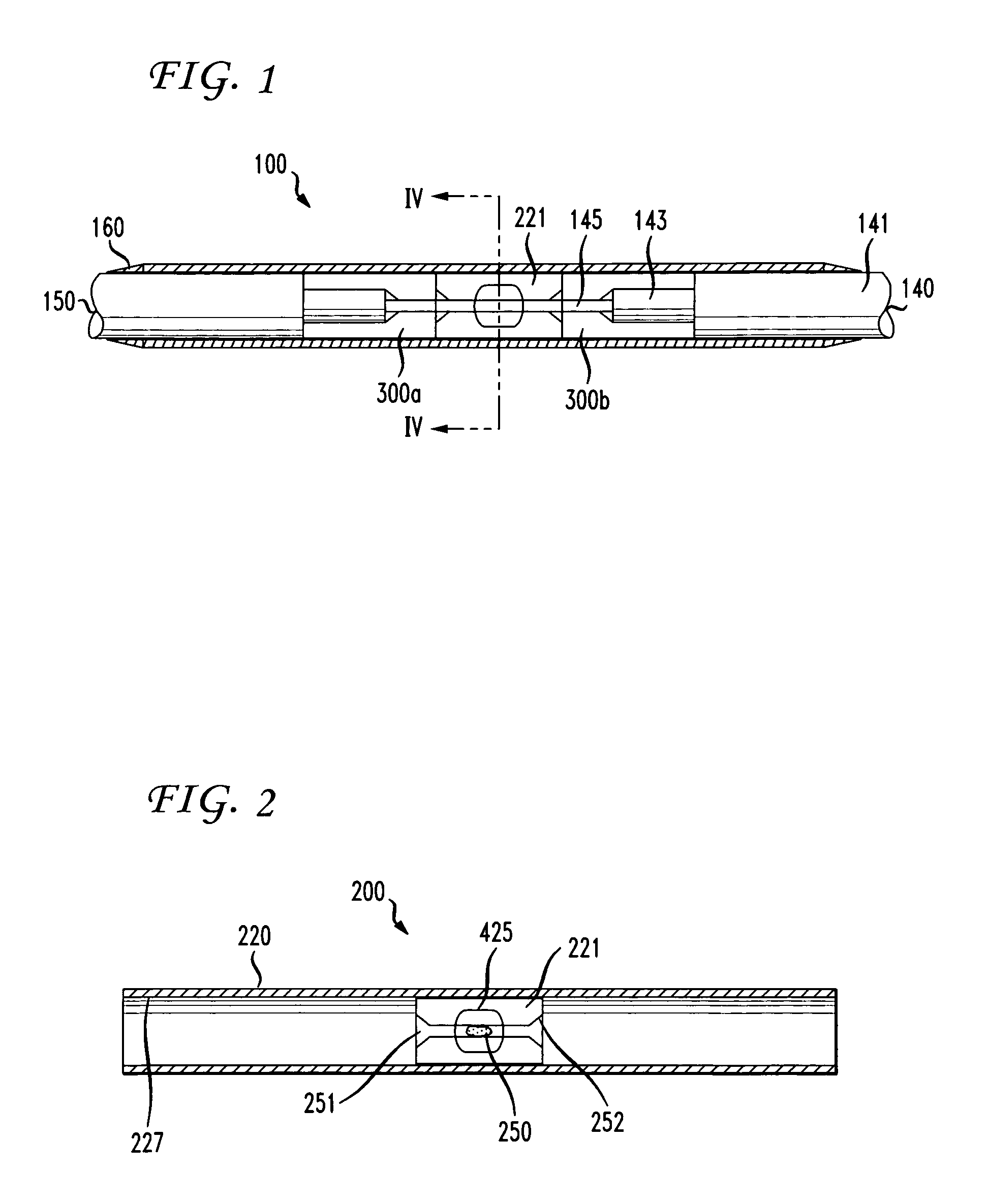
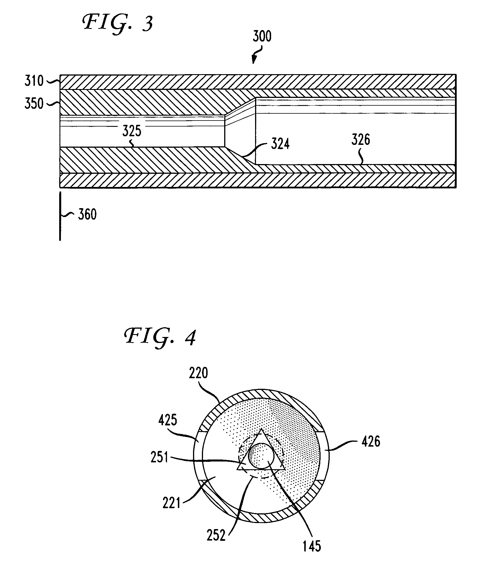
[0064]The present invention overcomes the above-described problems with several methods and apparatuses relating to a novel multimode mechanical splice. A splice assembly 100 according to one embodiment of the invention with optical fiber cables 140, 150 in place is shown in FIG. 1. As used herein, the term “optical fiber cable” refers to an optical fiber core together with the protective and isolating layers surrounding the fiber. A typical optical fiber cable 140, shown separately in FIG. 7, includes an optical fiber core 145, a hermetic coating (not shown) of polyimide applied directly to the optical fiber core, an inner jacket layer 143 typically comprising a modified ETFE (ethylene-tetrafluoroethylene) fluoropolymer such as Tefzel® manufactured by DuPont, an aramid fiber mesh strength member (fabricated, for example, from Dupont Kevlar® fibers) 142 and an outer jacket 141.

[0065]Returning to FIG. 1, the splice assembly 100 is shown joining the ends of two optical fiber cables 14...


PUM


Abstract

A splicing method and splicing kit are suitable for creating a multimode mechanical splice. The splice may be used, for example, in Aircraft Battle Damage Repair operations. The splice utilizes two cylindrical inner crimp sleeves and an outer crimping assembly. The inner crimp sleeves are placed over prepared fiber cable ends, and the fiber core is cleaved. The cable ends are then inserted into an outer cannula of the outer crimping assembly. The cannula guides the inner crimp sleeves, and the cleaved fiber ends enter a glass ferrule in the cannula. The glass ferrule has a triangular bore containing an index matching gel. A window in the cannula and a magnifying viewer are provided to visually confirm the splice quality. The fibers may be cleaved by forming a circumferential score on the fiber.

Description

STATEMENT REGARDING FEDERALLY SPONSORED RESEARCH OR DEVELOPMENT[0001]The U.S. Government has a paid-up license in this invention and the right in limited circumstances to require the patent owner to license others on reasonable terms as provided for by the terms of Contract No. F33615-02-D-2299 awarded by the United States Department of Defense / United States Air Force.FIELD OF THE INVENTION[0002]The present invention relates generally to the problem of splicing optical fibers. More specifically, the invention relates to splicing optical fibers under adverse conditions such as limited working space, limited available time and high quality requirements. Those conditions are typically encountered in Aircraft Battle Damage Repair operations.BACKGROUND OF THE INVENTION[0003]Fiber optics offers the avionics industry advantages of weight and stealth compared to traditional wiring. Local area fiber cables can provide a means of communication between the various avionics modules. The Air For...

Claims


Application Information

Patent Timeline
Patent Type & Authority Patents(United States)
IPC IPC(8): G02B6/255
CPCG02B6/3801G02B6/25G02B6/2558G02B6/3803
Inventor SOLOMON, THOMASJOHNSON, DONALDMERSCH, STEVEN
Owner AMERICAN TELEPHONE & TELEGRAPH CO
Why Eureka
Try Eureka