
Pulse position based-chaotic modulation (PPB-CM) communication system and method

a communication system and position-based technology, applied in multi-frequency code systems, synchronisation signal speed/phase control, duplex signal operation, etc., can solve the problem that the dcsk communication system is not suitable for the ieee 802.15.4a, the receiver b>70/b> cannot predefine the threshold, and the delay line is long. problem, to achieve the effect of accurate and easy determining a communication signal and simple implementation

Active Publication Date: 2012-01-24
SAMSUNG ELECTRONICS CO LTD
View PDF4 Cites 2 Cited by
  • Summary
  • Abstract
  • Description
  • Claims
  • Application Information

AI Technical Summary

Benefits of technology

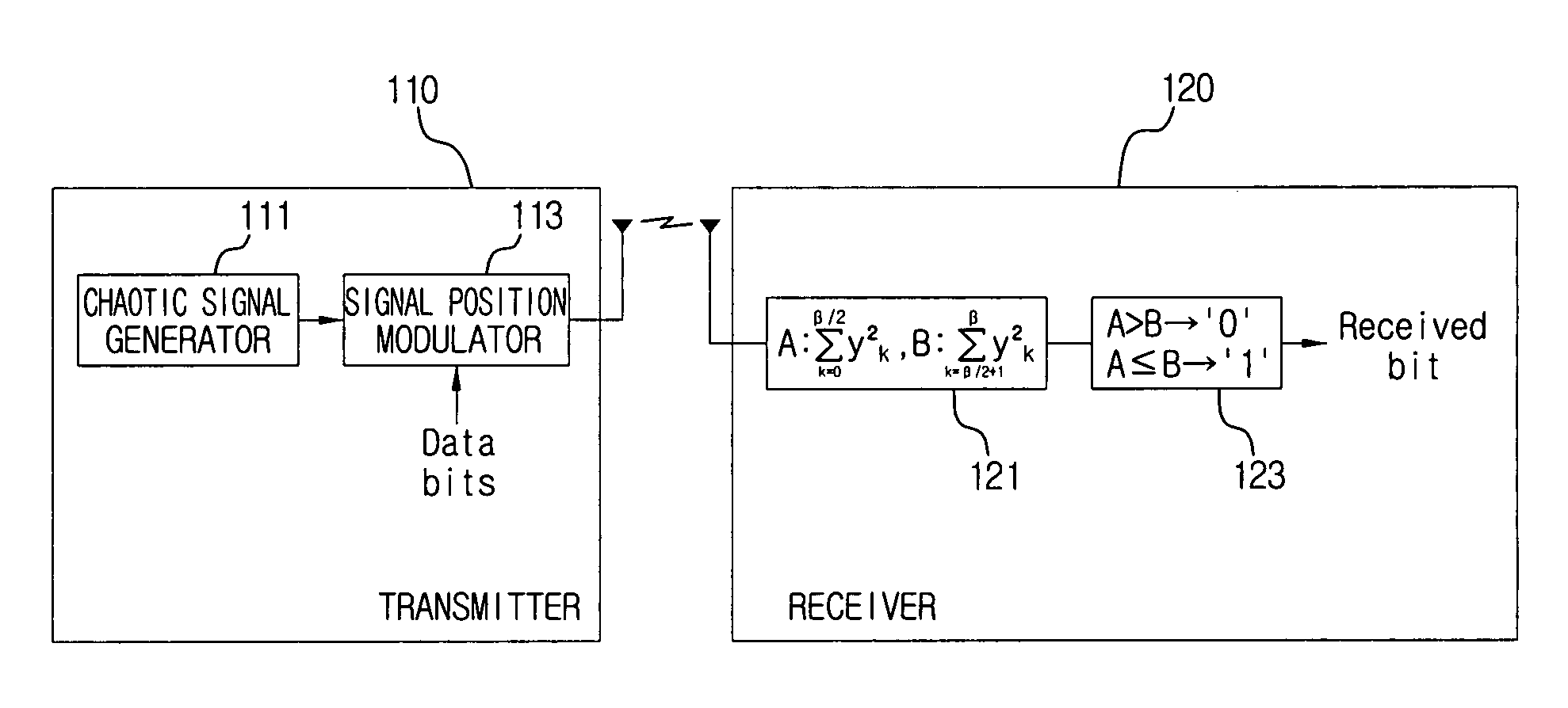
The present invention provides a PPB-CM communication system and method that can accurately and easily determine a communication signal with a simple implementation. The system includes a transmitter that splits a symbol period, inserts a data signal in one of the parts, and transmits the communication signal. The receiver then determines the bit information of the symbol period by calculating the energy value of the signals in the symbol period and comparing it to a predetermined threshold. This allows for easy identification of the data signal and ensures reliable communication.

Problems solved by technology

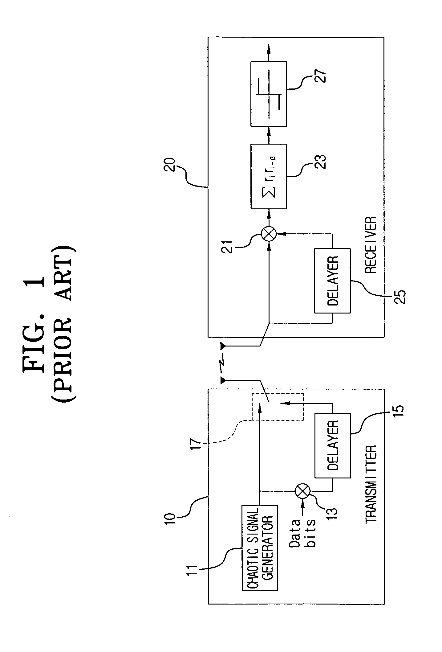
However, the DCSK communication system needs a lengthy delay line (20 m) to delay the reference signal by ½ Ts when generating the data signal.
Hence, the DCSK communication system is not suitable for the IEEE 802.15.4a environment which aims to provide a sensor network.
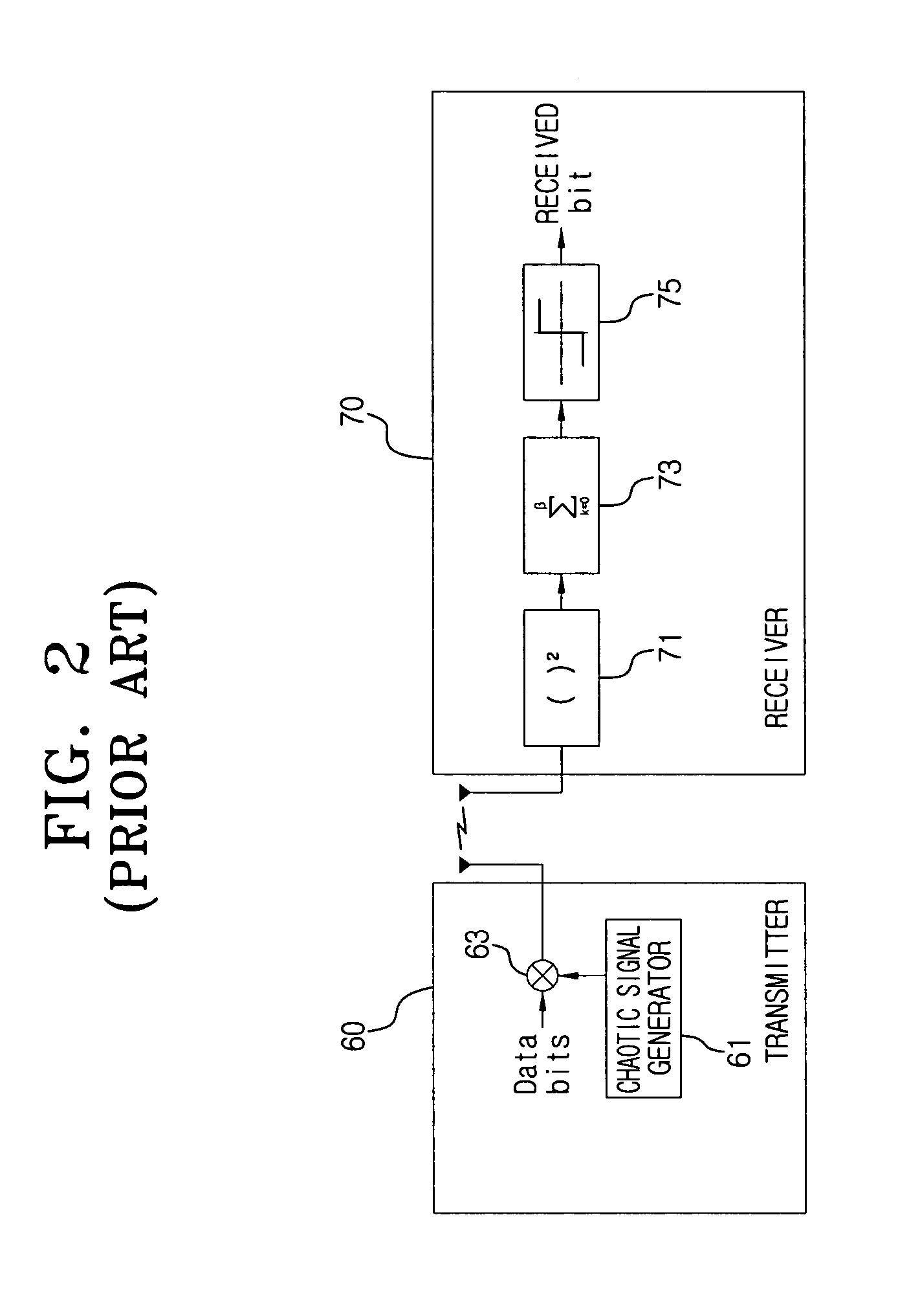
Yet, it is hard for the receiver 70 to predefine the threshold because it does not know the magnitude of the communication signal received from the transmitter 60.
However, it is hard to measure merely the pure noise because the channel power affects the guard interval as the communication signal passes through the channel in the channel environment.
Thus, a simulation of the method using the noise energy of the guard interval shows a performance degradation when the noise energy is greater than a specific number, and the error flow when the noise energy is smaller than the specific number.

Method used


Image

  • Pulse position based-chaotic modulation (PPB-CM) communication system and method
  • Pulse position based-chaotic modulation (PPB-CM) communication system and method
  • Pulse position based-chaotic modulation (PPB-CM) communication system and method

Examples


Embodiment Construction

[0053]Reference will now be made in detail to illustrative embodiments of the present invention, examples of which are illustrated in the accompanying drawings, wherein like reference numerals refer to the like elements throughout. The embodiments are described below to explain the present invention by referring to the figures.

[0054]FIG. 3 is a block diagram of a pulse position based-chaotic modulation (PPB-CM) communication system according to an embodiment of the present invention.

[0055]The PPB-CM communication system includes a transmitter 110 and a receiver 120.

[0056]The transmitter 110 includes a chaotic signal generator 111 and a signal position modulator 113.

[0057]The chaotic signal generator 111 generates a chaotic signal having characteristics to carry data. Generally, a chaos dynamic system is utilized. The chaotic signal generator 111 generates the chaotic signal directly in a frequency band for data transmission, from a preset radio frequency, microwave, infrared ray, vi...


PUM


Abstract

A PPB-CM communication system and method. The PPB-CM communication system includes a transmitter which splits a symbol period, which is a transmission unit of a communication signal, into at least a pair of parts, inserts a data signal into one of the parts, and transmits a communication signal having the data signal inserted; and a receiver which receives the communication signal from the transmitter and determines bit information of the symbol period according to which part of the symbol period has the data signal inserted, as determined by comparison of energy levels of the parts. Accordingly, a separate threshold is not required to determine the data bit of the symbol period. Thus, the communication signal can be accurately determined. Also, the communication system can be simply implemented without need of a delay line.

Description

CROSS-REFERENCE TO RELATED APPLICATIONS[0001]This application claims the benefit under 35 U.S.C. §119 (a) from Korean Patent Application No. 2005-119382 filed on Dec. 8, 2005 in the Korean Intellectual Property Office, the entire disclosure of which is incorporated herein by reference.BACKGROUND OF THE INVENTION[0002]1. Field of the Invention[0003]The present invention generally relates to a pulse position based-chaotic modulation (PPB-CM) communication system and method. More particularly, the present invention relates to a PPB-CM communication system and method for determining the data bits of a communication signal more accurately, with a simple implementation.[0004]2. Description of the Related Art[0005]The IEEE 802.15.4a task group is the location-aware low-power sensor network standardization group. Location-aware low-power sensor networking is a next generation communication technique in which the location awareness capability and low power requirements are added to the combi...

Claims


Application Information

Patent Timeline
Patent Type & Authority Patents(United States)
IPC IPC(8): H04L9/00
CPCH04L25/4902H04L27/001H04L7/00H04L7/10
Inventor KIM, JAE-HYONKIM, YOUNG-HWANKIM, HYUNKUKPARK, HYUNCHEOLLEE, SEONG-SOOSON, JAESEUNG
Owner SAMSUNG ELECTRONICS CO LTD
Learn More