Series resonant converter

a series resonant converter and converter technology, applied in the direction of electric variable regulation, process and machine control, instruments, etc., can solve the problems of reducing the power supply of the series resonant converter, increasing the cost, and deviating the resonant current waveform, so as to reduce noise, reduce power loss, and reduce the power loss

Active Publication Date: 2012-01-31
ORIGIN CO LTD
View PDF8 Cites 11 Cited by
  • Summary
  • Abstract
  • Description
  • Claims
  • Application Information

AI Technical Summary

Benefits of technology

[0010]The present invention has an object of improving a resonant current waveform to be a sinusoidal wave or nearly a sinusoidal waveform by changing the capacity of resonant capacitance in a serial resonant circuit composed of a resonant inductance means and a resonant capacitor automatically when the load voltage and the load current change greatly, thereby raising the power efficiency of a series resonant converter over a broad load range.
[0013]Since, for a case of a constant power load, the present invention makes a resonant current waveform to be a sinusoidal wave or nearly a sinusoidal waveform by changing the resonant capacitance in a serial resonant circuit composed of a resonant inductance and a resonant capacitor automatically, when the load voltage and the load current change greatly, it is possible to reduce power loss of the series resonant converter and reduce noise without using a resonant capacitance switching mechanism or the like. Furthermore, in a high load impedance state, since the secondary-side resonant capacitors that are connected to each other in series and the rectifying diodes that are connected to each other in series configure a voltage doubler recitification circuit, the recovery current due to the feedback diodes in parallel to the switching elements does not flow, a result of which recovery loss, noise, and the like do not occur.
[0014]In addition, since the series resonant converter circuit according to another embodiment of the present invention is further configured in a circuit configuration that does not allow current that feedbacks to the DC power supply from the resonant circuit, i.e. leading current, to flow, and so that the voltage of the primary-side resonance capacitor does not exceed the DC power supply voltage, recovery current does not flow to the feedback diode even in the low load condition. Therefore, it is possible to further reduce power loss as well as reduce noise.

Problems solved by technology

These discharge loads often require constant power.
However, for switching of the tap, a switching operation has to be done by opening a housing of the power supply unit, which is troublesome since it requires time and effort, while safety must be ensured by confirming the discharge of residual charge upon switching.
In this case, since the power of a transformer is substantially proportional to the product of the maximum voltage and the maximum current, a transformer having a power capacity with 1.6 kW is needed, and the power of the transformer becomes approximately double the transfer power of 800 W. This is obviously not cost-effective since the entire power supply unit becomes larger and heavier, which leads to an increase in cost.
However, a case of using a resonant converter circuit as a DC power supply for a vacuum device has the following problem.
However, the resonant current waveform deviates from the sinusoidal waveform accompanying the gradual decline in the DC output current from the rated voltage.
For example, in a case in which the output voltage is lower to approximately half the rated voltage, and the output current must be amplified up to approximately double the rated current, since the resonant current of the resonant converter becomes an AC waveform that deviates from the sinusoidal waveform according to the principles of resonance, the power efficiency of the resonant converter circuit declines and noise becomes large.

Method used


Image

  • Series resonant converter
  • Series resonant converter
  • Series resonant converter

Examples


first embodiment

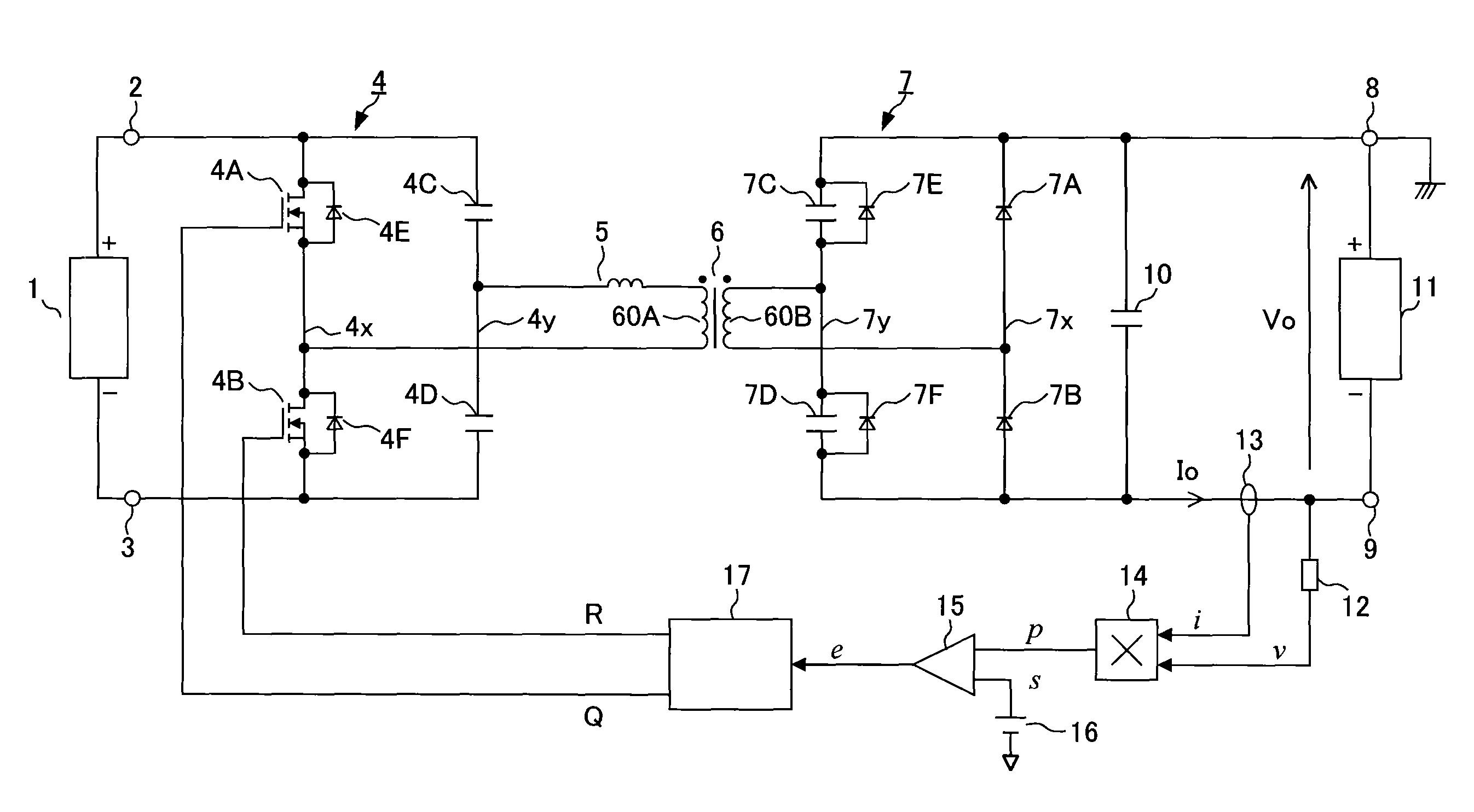
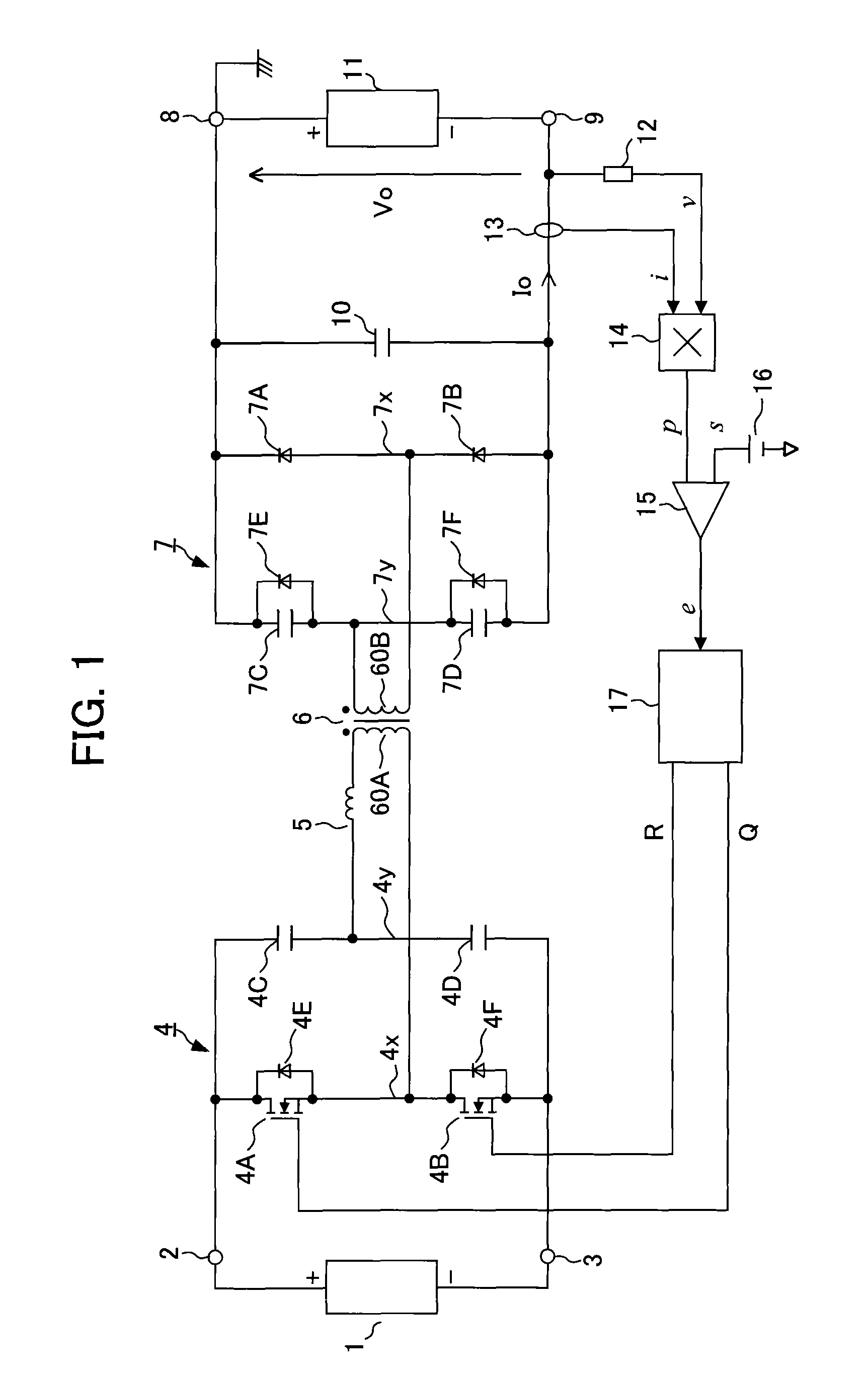
[0027]A series resonant converter circuit of a first embodiment according to the present invention is explained with reference to FIGS. 1 to 6G. In FIG. 1, a DC power supply 1 is connected between a DC input terminal 2 of a positive terminal and a DC input terminal 3 of a negative terminal. The DC power supply 1 is a common device that is composed of a rectification circuit that rectifies single phase or three-phase AC power into DC power and a filter circuit that smoothes the DC power. In addition, the DC power supply 1 may be an energy source such as a battery or electric generator. Furthermore, the DC power supply 1 may be a rectifier including a PFC (power factor improvement circuit). In this case, an input voltage of the series resonant converter of the present invention, which is connected to a subsequent stage of the PFC, is stabilized. Therefore, since only load fluctuations should be considered regarding an operational aspect thereof, which is advantageous to the understand...

third embodiment

[0075]FIG. 9 shows a series resonant converter circuit in which synchronous rectification is applied to a secondary-side multi-functional rectification circuit 7. The rectifying diodes 7A and 7B of the secondary-side multi-functional rectification circuit 7 in the previous embodiment are replaced with rectifying MOSFETs 7G and 7H. 7I and 7J indicate internal diodes that the rectifying MOSFET 7G and MOSFET 7H respectively include. The rectifying MOSFETs 7G and 7H are alternately driven by gate signals q and r from a control circuit 17. When MOSFETs are used as the switching elements 4A and 4B of the primary-side inverter circuit 4, the MOSFET 4A of the inverter circuit 4 and the rectifying MOSFET 7G of the multi-functional rectification circuit 7 are driven by the same gate signals Q and q, and the MOSFET 4B of the inverter circuit 4 and the rectifying MOSFET 7H of the multi-functional rectification circuit 7 are driven by the same gate signals R and r.

[0076]In this series resonant ...

fifth embodiment

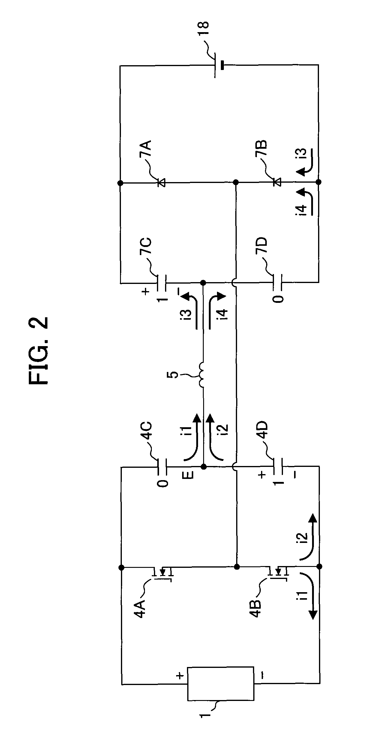
[0080]In the series resonant converter when the switching element 4A turns on, the primary-side resonant capacitor 4D is charged through a primary winding wire 60A of a transformer 6 and the resonant inductance means 5 with an upper terminal of the primary-side resonant capacitor 4D being positive terminal In addition, when the switching element 4B turns on, the charge of the primary-side resonant capacitor 4D is discharged through the primary-side winding sire 60A of the transformer 6 and the resonant inductance means 5.

[0081]When the primary-side resonant capacitor 4D is charged with reverse polarity, i.e. when charged so that the voltage of the upper terminal of the primary-side resonant capacitor 4D in FIG. 11 is lower than the voltage of the lower terminal thereof, the diode 4H in parallel to the primary-side resonant capacitor 4D conducts and prevents a reverse polarity charging of the primary-side resonant capacitor 4D. Therefore, since the series resonant converter circuit ...


PUM


Abstract

A series resonant converter circuit that reduces power loss is provided that includes an inverter circuit having at least a pair of first and second switching elements that is connected between DC input terminals, a transformer connected to this inverter circuit, a resonant inductance means that are connected in series to a primary winding wire or a secondary winding wire of the transformer, a primary-side resonant capacitor that is connected in series to the resonant inductance means through the first or second switching element, first and second secondary-side resonant capacitors that are connected to each other in series between the DC input terminals, first and second unidirectional elements that are connected to each other in series between the DC output terminals, and a resonant inductance means that cooperates with resonant capacitance from the primary-side resonant capacitor and the first and second secondary-side resonant capacitors to resonate in series.

Description

CROSS-REFERENCE TO RELATED APPLICATION[0001]The present application claims the benefit of priority of Japanese Patent Application No. 2009-270337, filed on Nov. 27, 2009, the content of which is hereby incorporated herein by reference.FIELD OF THE INVENTION[0002]The present invention relates to a series resonant converter circuit that utilizes a serial resonant effect of a resonant inductance means and a resonant capacitor, and more specifically relates to a series resonant converter circuit having characteristics that are suitable for a direct current sputtering power supply that is suited to a discharge load such as plasma, a capacitor of which load voltage drastically changes, and a charging DC power supply such as a battery.BACKGROUND OF THE INVENTION[0003]As a discharge load using discharge energy, there are various laser devices, a discharge lamp lighting device, a strobe device, an electro-discharge machining device, a fusion splicing device of optic fiber, and a vacuum devic...

Claims


Application Information

Patent Timeline
Patent Type & Authority Patents(United States)
IPC IPC(8): H02M3/335
CPCH02M3/335Y02B70/1433Y02B70/10
Inventor UENO, SHINGOOMAKI, SHINICHISAITO, ATSUSHIWATANABE, KIYOMI
Owner ORIGIN CO LTD
Why Eureka
Try Eureka