Stent crimping device

a crimping device and stent technology, applied in the direction of metal-working holders, large fixed members, supporters, etc., can solve the problems of obstructing arteries, non-uniform stent crimping, and stent occlusion, etc., to achieve high usefulness, perform fairly efficiently and quickly

Active Publication Date: 2012-02-14
ABBOTT LAB VASCULAR ENTERPRISE
View PDF19 Cites 18 Cited by
  • Summary
  • Abstract
  • Description
  • Claims
  • Application Information

AI Technical Summary

Benefits of technology

[0013]More precisely, the present invention is directed to a tool for crimping a prosthesis onto a catheter comprising a plurality of wheels, wherein each wheel is rotatably mounted on an axle. Each wheel has an outer circumferential surface configured to apply a radially inward force on the prosthesis. The wheels are mounted so as to be positionable in relation to each other such that a diameter of each wheel radiates outwardly from a central axis, wherein the outer circumferential surfaces of the wheels are positionable equidistant from the axis by a first smallest possible distance (“S1” as in FIG. 2B) to define a first space that includes the axis. This configuration permits a prosthesis to be passed between the wheels which apply a radially inward force on the prosthesis to crimp the prosthesis to a smaller diameter. A first number out of the plurality of wheels are mounted so as to be restrained from further advancing toward the axis, thereby leaving a number of remaining wheels mounted to be capable of further advancing toward the axis, wherein the outer circumferential surfaces of the remaining wheels are positionable equidistant from the axis by a second smallest possible distance (“S2” as in FIG. 3B) to define a second space that includes the axis, the second space being smaller than the first space. In this way, the remaining wheels are advantageously positioned to further crimp the prosthesis to an even smaller diameter, which would otherwise be impossible if the first number of wheels were not configured to be restrained from further advancing toward the axis.
[0014]In another aspect, the invention includes a method of crimping a prosthesis having an elongate axis. The method comprises positioning a plurality of wheels about the prosthesis so that an outer circumferential surface of each wheel is in contact with the prosthesis; moving the prosthesis along the elongate axis; rotating each of the wheels while maintaining contact between the wheels and the prosthesis, thereby reducing the diameter of the prosthesis; causing a first number of the wheels to no longer be in contact with the prosthesis to leave a first remainder of wheels in contact with the prosthesis; and rotating each of the first remainder of wheels while maintaining contact between each of the first remaining wheels and the prosthesis, thereby further reducing the diameter of the prosthesis. This method has a similar advantage to the foregoing apparatus, of sequentially crimping the prosthesis to a final diameter, using a first number of wheels and then subsequently a second smaller number of wheels to finish off the crimping to the desired final diameter.
[0016]And in yet a further aspect, the invention includes a method of crimping a prosthesis having an elongate axis. The method comprises positioning a first plurality of wheels about the prosthesis so that an outer circumferential surface of each wheel is in contact with the prosthesis, each surface having a first width; moving the prosthesis along the elongate axis; rotating each of the wheels while maintaining contact between the wheels and the prosthesis, thereby reducing the diameter of the prosthesis. Then, removing all of the first plurality of wheels from being in contact with the prosthesis; positioning a second plurality of wheels about the prosthesis so that an outer circumferential surface of each of the second plurality is in contact with the prosthesis, each surface having a second width less than the first width; moving the prosthesis along the elongate axis; rotating each of the second plurality of wheels while maintaining contact between the second plurality of wheels and the prosthesis, thereby further reducing the diameter of the prosthesis.
[0017]An even further aspect of the invention includes a system for crimping a prosthesis comprising a first plurality of wheels, wherein each wheel is rotatably mounted on an axle, and each axle of the first plurality lies in the same first plane. Each wheel has an outer circumferential surface and the wheels are positioned in relation to each other such that a diameter of each wheel radiates outwardly from a central axis, whereby the outer circumferential surfaces of the wheels define a first space that includes the central axis, the first space being configured to receive the prosthesis during crimping. A second plurality of wheels is provided wherein each wheel is rotatably mounted on an axle, and each axle of the second plurality lies in the same second plane, the second plane being spaced apart from the first plane by a distance. Each wheel has an outer circumferential surface and the wheels are positioned in relation to each other such that a diameter of each wheel radiates outwardly from the central axis, whereby the outer circumferential surfaces of the wheels define a second space that includes the central axis, the second space being configured to receive the prosthesis during crimping. Significantly, the first space is larger than the second space. By this structure, a prosthesis may advantageously be crimped when the prosthesis is unusually long. The spaced apart sets of wheels allow for greater control over the crimping process as the prosthesis passes from one set to the next.
[0018]Finally, the invention includes a method of crimping a prosthesis having an elongate axis comprising moving the prosthesis along its axis between a first plurality of wheels so that an outer circumferential surface of each of the first plurality of wheels is in contact with the prosthesis; rotating each of the wheels while maintaining contact between the wheels and the prosthesis, thereby reducing the diameter of the prosthesis by a first amount; passing the prosthesis from between the first plurality of wheels to between a second plurality of wheels, the second plurality of wheels being situated adjacent the first plurality; moving the prosthesis between the second plurality of wheels so that an outer circumferential surface of each of the second plurality of wheels is in contact with the prosthesis; rotating each of the second plurality of wheels while maintaining contact between the wheels and the prosthesis, thereby further reducing the diameter of the prosthesis by a second amount. In this embodiment, the invention has advantages similar to those of the previously described embodiment, in which a long prosthesis may be crimped under improved control of one set of wheels adjacent a second set of wheels.
[0019]The present invention is thus capable of homogeneously and precisely crimping a stent onto a balloon catheter. Such a crimping tool is highly useful to cardiologists and radiologists, for example. Such physicians are constantly concerned with proper deployment of the stent within the patient that it is desirable to have a consistently and reliably crimped stent. The present invention tool is further a time saver, because the stent crimping procedure can be performed fairly efficiently and quickly. Indeed, these and other advantages of the present invention will become apparent from the following detailed description thereof when taken in conjunction with the accompanying exemplary drawings.

Problems solved by technology

Non-uniform crimping can result in sharp edges being formed along the now uneven surface of the crimped stent.
Furthermore, non-uniform stent crimping may not achieve the desired minimal profile for the stent and catheter assembly.
Where the stent is not reliably crimped onto the catheter, the stent may slide off the catheter and into the patient's vasculature prematurely as a loose foreign body, possibly causing obstructed arteries, blood clots in the vasculature, including thrombosis.
This crimping is often done by hand, which can be unsatisfactory due to the uneven application of force resulting in non-uniform crimps or loosely fitted stents which pose a critical danger to the patient.
In addition, it is difficult to visually judge when a uniform and reliable crimp has been applied.
Some self-expanding stents are difficult to load by hand onto a delivery device such as a catheter.
Furthermore, the more the stent is handled the higher the likelihood of human error, which would be antithetical to a properly crimped stent.
While the prior art devices are suitable for crimping stents onto balloon catheters, they suffer from problems such as non-uniform crimping forces, especially for long stents, resulting in non-uniform crimps.

Method used


Image

  • Stent crimping device
  • Stent crimping device
  • Stent crimping device

Examples


Embodiment Construction

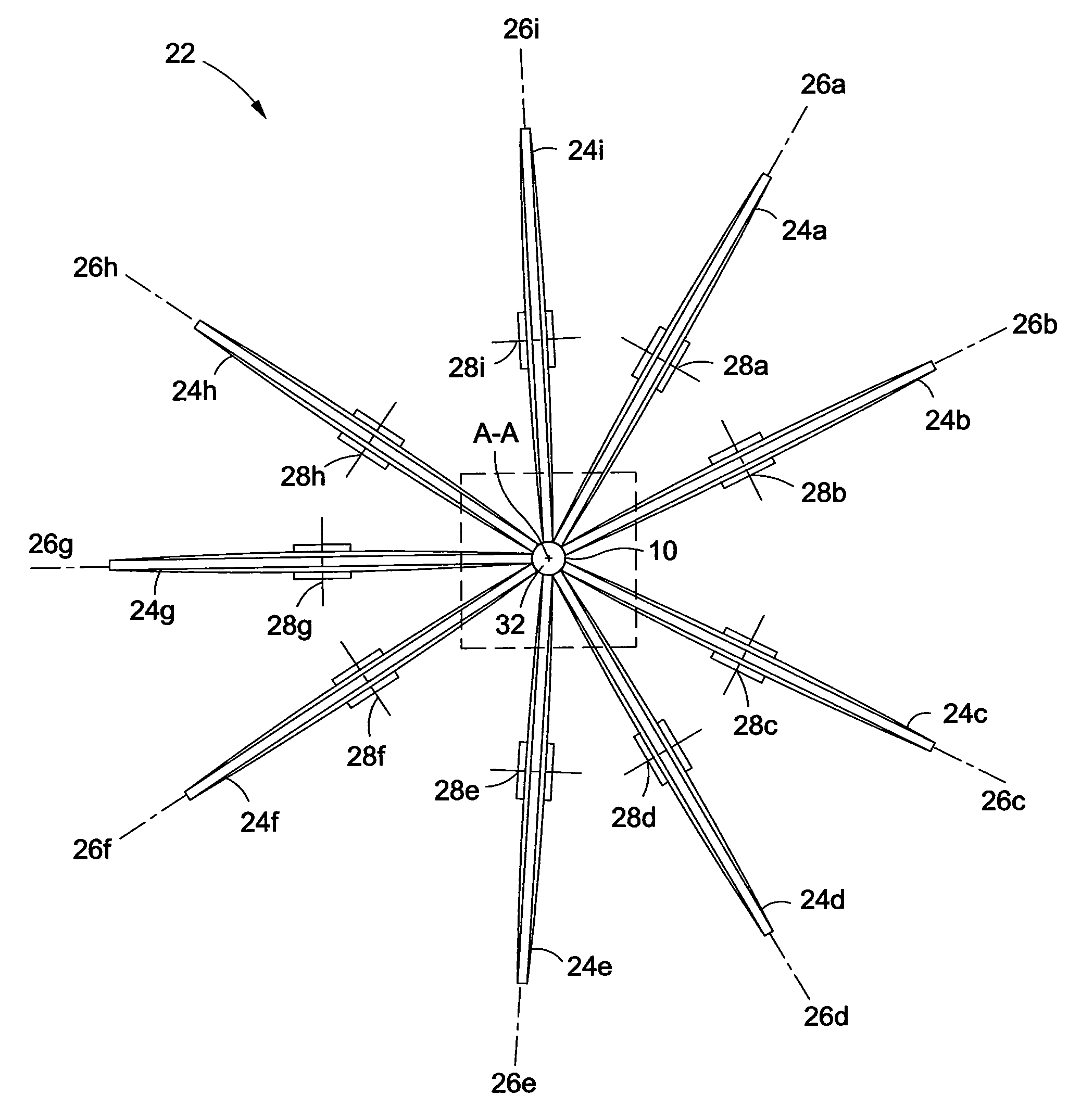
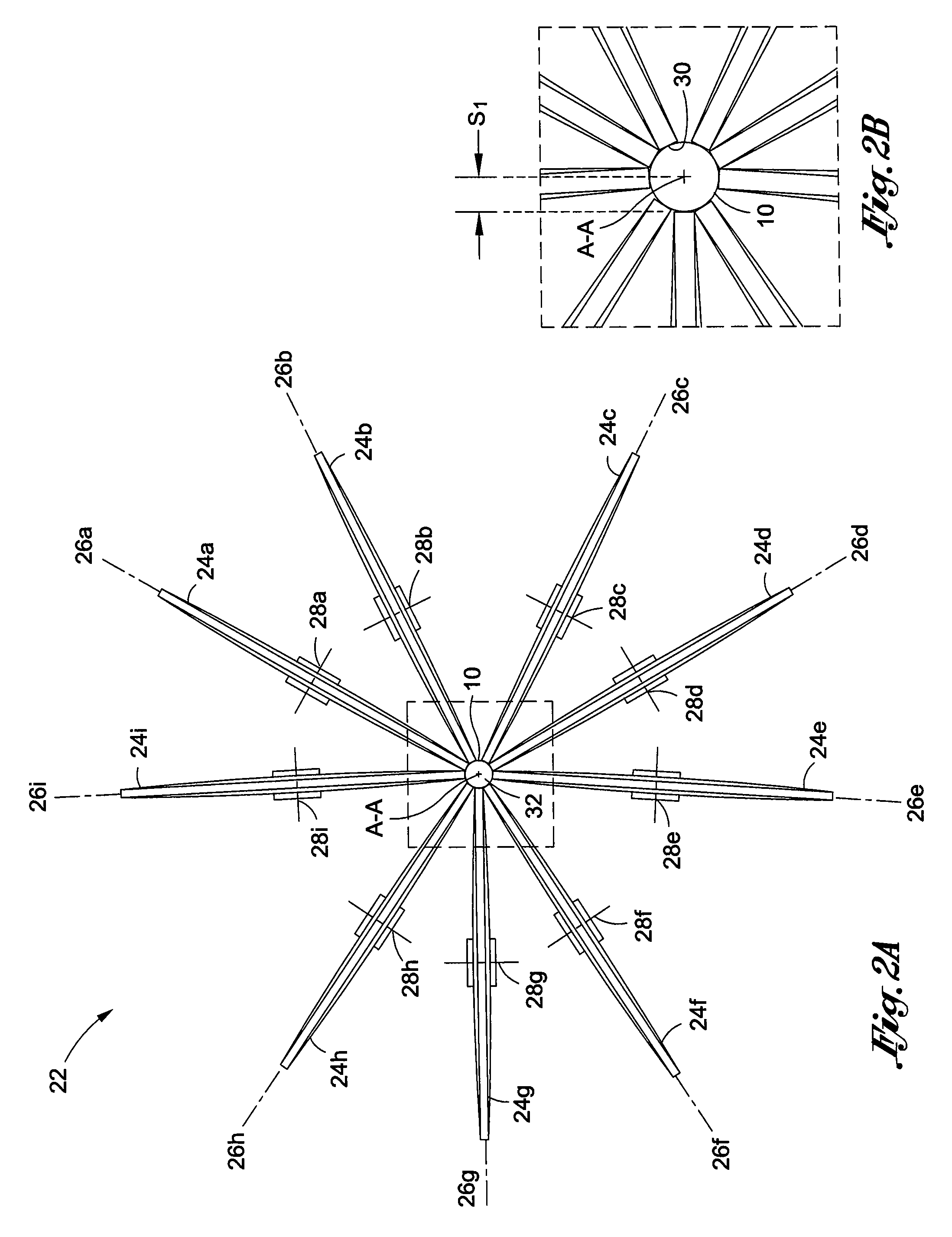
[0031]With reference to FIGS. 2-9, there is shown by way of exemplification and not limitation a prosthesis or stent crimping device having features of the present invention, generally indicated by the numeral 22.

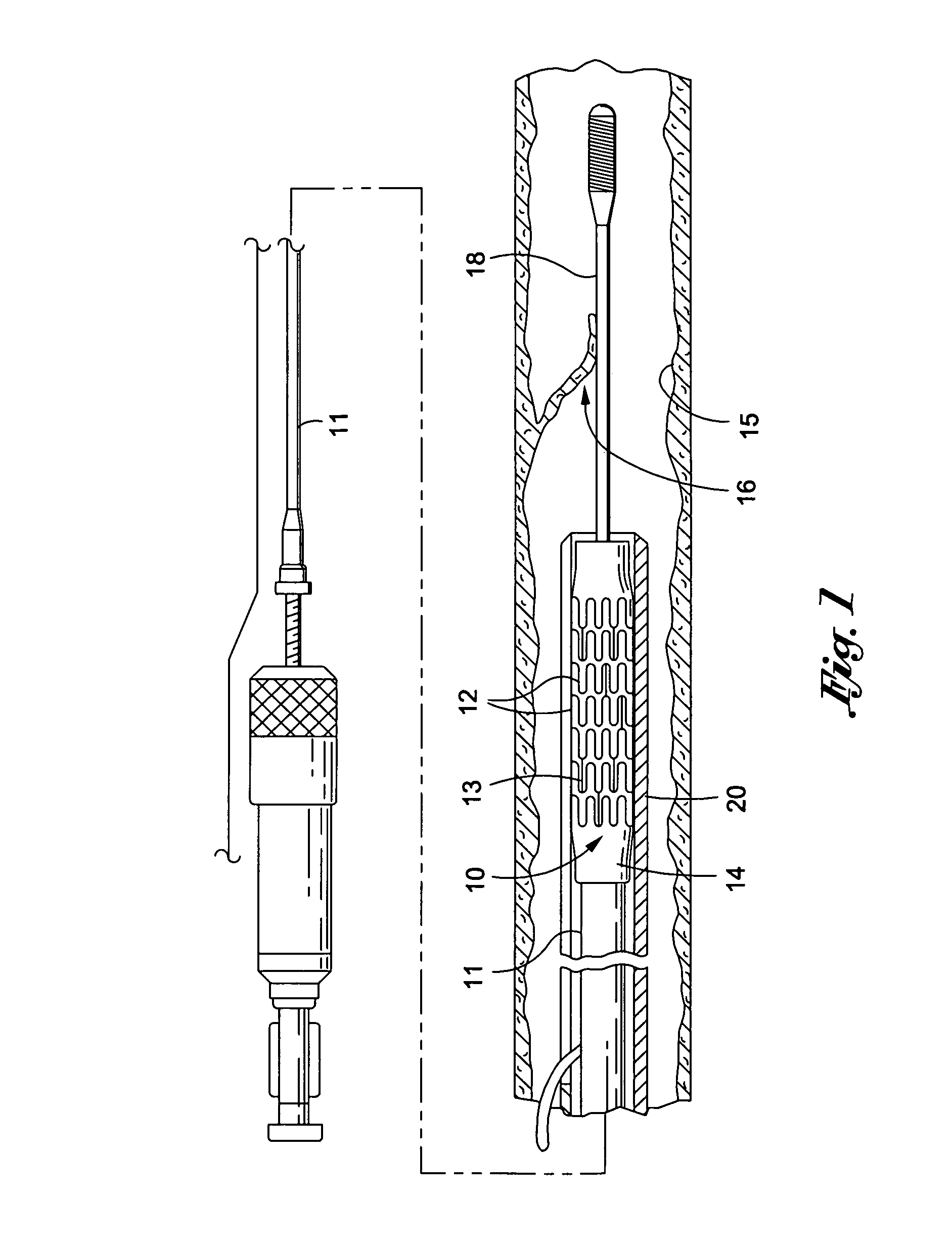
[0032]Before the invention is described, several aspects of related technology and human anatomy are described with reference to FIG. 1, which illustrates an intravascular stent 10 which is mounted onto a delivery catheter 11. The stent 10 generally comprises a plurality of radially expandable cylindrical elements 12 disposed generally coaxially and interconnected by members 13 disposed between adjacent cylindrical elements 12. Delivery catheter 11 has an expandable portion or balloon 14 for expanding stent 10 within coronary artery 15 or other vessel such as saphenous veins, carotid arteries, arteries, and veins. Artery 15, as shown in FIG. 1, has a dissected lining 16 which has occluded a portion of the arterial passageway.

[0033]The delivery catheter 11 onto which the ste...


PUM

PropertyMeasurementUnit
diameteraaaaaaaaaa
distanceaaaaaaaaaa
pressuresaaaaaaaaaa

Abstract

A system for crimping a prosthesis is disclosed, comprising a plurality of wheels. Each wheel has an outer circumferential surface configured to be placed in contact with the prosthesis. When in contact with the prosthesis, each wheel is configured to be rotated, thereby to apply a radially inward force on the prosthesis so as to reduce the diameter of the prosthesis. More than one set of wheels may be provided, so that the prosthesis is crimped first by one set of wheels, then by a subsequent set of wheels.

Description

BACKGROUND OF THE INVENTION[0001]The present invention relates to an apparatus for loading a tubular graft or prosthesis, such as a stent, onto the distal end of a catheter assembly of the kind used, for example, in percutaneous transluminal coronary angioplasty (PTCA) or percutaneous transluminal angioplasty (PTA) procedures.[0002]In typical PTCA procedures, a guiding catheter is percutaneously introduced into the cardiovascular system of a patient through the brachial or femoral arteries and advanced through the vasculature until the distal end of the guiding catheter is in the ostium. A guide wire and a dilatation catheter having a balloon on the distal end are introduced through the guiding catheter with the guide wire sliding within the dilatation catheter. The guide wire is first advanced out of the guiding catheter into the patient's coronary vasculature and the dilatation catheter is advanced over the previously advanced guide wire until the dilatation balloon is properly po...

Claims


Application Information

Patent Timeline
Patent Type & Authority Patents(United States)
IPC IPC(8): B23P11/00B21D41/00B23Q1/00B21J7/16
CPCA61F2/958B25B27/10A61F2002/9522Y10T29/53709Y10T29/49925Y10T29/49908Y10T29/53991A61F2/9522
Inventor VOELKL, CLAUS
Owner ABBOTT LAB VASCULAR ENTERPRISE
Why Eureka
Try Eureka