
Self-oscillating UWB emitter-detector

a self-oscillating, emitter-detector technology, applied in the field of radar detection circuits, can solve the problems of excessive bandwidth, too large bandwidth for some applications, impulse-type samplers, etc., and achieve the effect of low noise and low level of local oscillator leakag

Active Publication Date: 2012-02-14
MCEWAN TECH
View PDF14 Cites 16 Cited by
  • Summary
  • Abstract
  • Description
  • Claims
  • Application Information

AI Technical Summary

Benefits of technology

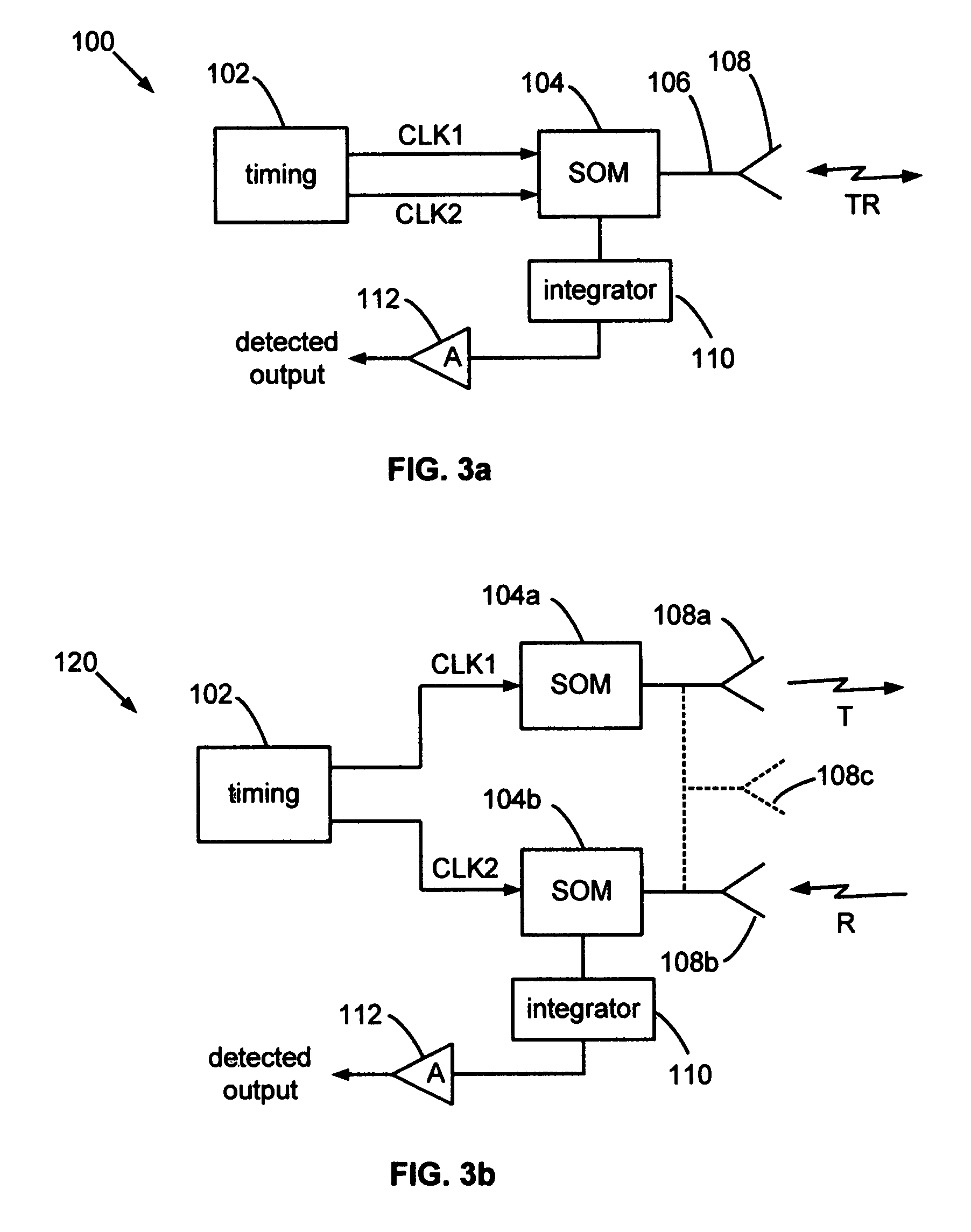
[0012]In a homodyne emitter-detector configuration, it is a self-oscillating emitter-detector radar system comprising: a timing system for producing a transmit and a receive dock signal; a SOM responsive to both dock signals and for producing RF oscillations that are phase-locked to each clock signal; an antenna coupled to the SOM for transmitting RF pulses produced by the SOM and for receiving UWB RF echoes and for providing UWB RF echo pulses to the SOM; and, an integrator coupled to the SOM for coherently integrating mixer pulses from the SOM and for producing a detected output signal. The self-oscillating emitter-detector radar system can provide an adjustable or a fixed delay between the transmit and receive clock signals for producing range-gated Doppler signals from the integrator. The self-oscillating emitter-detector radar system can also provide a swept delay between the transmit and receive clock signals for producing video pulse signals from the integrator.
[0013]In a heterodyne emitter-detector configuration, it is a self-oscillating emitter-detector radar system, comprising: a timing system for producing a transmit and a receive dock signal; a transmit SOM responsive to the transmit dock signal for producing RF oscillations that are phase-locked to the transmit clock signal; an antenna coupled to the first SOM for transmitting the RF self-oscillations; a receive SOM responsive to the receive clock signal for producing mixer RF oscillations that are phase-locked to the receive clock signal; an antenna coupled to the second SOM for receiving UWB RF echoes and for providing UWB RF echo pulses to the receive SOM; and, an integrator coupled to the second SOM for coherently integrating mixer pulses from the second SOM and for producing a detected output signal. The self-oscillating emitter-detector radar system can provide an adjustable or a fixed delay between the transmit and receive clock signals for producing range-gated Doppler signals from the integrator. The self-oscillating emitter-detector radar system can also provide a swept delay between the transmit and receive clock signals for producing video pulse signals from the integrator.
[0014]Objects of the present invention are: (1) to provide a sensitive, simple, and low-cost, RF pulse detection system for UWB pulsed radar, TDR and laser ranging systems; (2) to provide a matched bandwidth UWB RF detector, (3) to provide a UWB RF detector that simultaneously incorporates low noise preamplification; (4) to provide a regulated, very low power level RF oscillator for low power transmitters and detectors; and (5), to provide a mixer with very low levels of local oscillator leakage.

Problems solved by technology

One potential limitation to impulse type samplers is their bandwidth can be too large for some applications, e.g., their bandwidth extends to zero, even though antennas cannot transmit and receive zero Hertz or relatively low frequencies (relative to their size).
This excessive bandwidth can, for example, substantially degrade S / N when operating in the 24-31 GHz UWB band while using a sampler that spans from DC to 31 GHz.
Prior approaches to matched bandwidth employ conventional filters and mixers, which are inefficient, bulky, costly, and require power-hungry preamplifiers.
Presently, there is no approach that provides a compact, low cost, low power, matched bandwidth, sampling solution.

Method used


Image

  • Self-oscillating UWB emitter-detector
  • Self-oscillating UWB emitter-detector
  • Self-oscillating UWB emitter-detector

Examples


Embodiment Construction

[0024]A detailed description of the present invention is provided below with reference to the figures. White illustrative component values and circuit parameters are given, other embodiments can be constructed with other component values and circuit parameters.

General Description

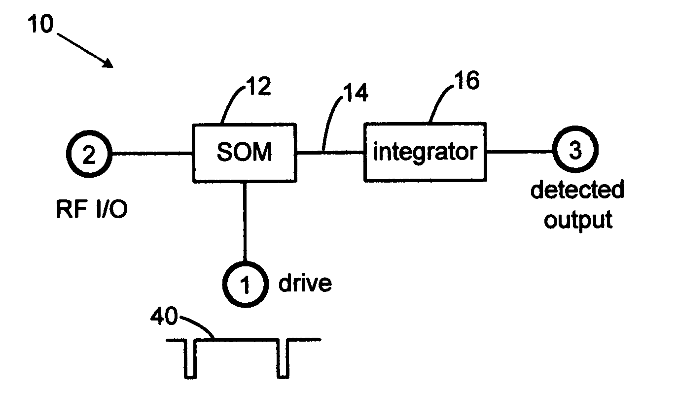
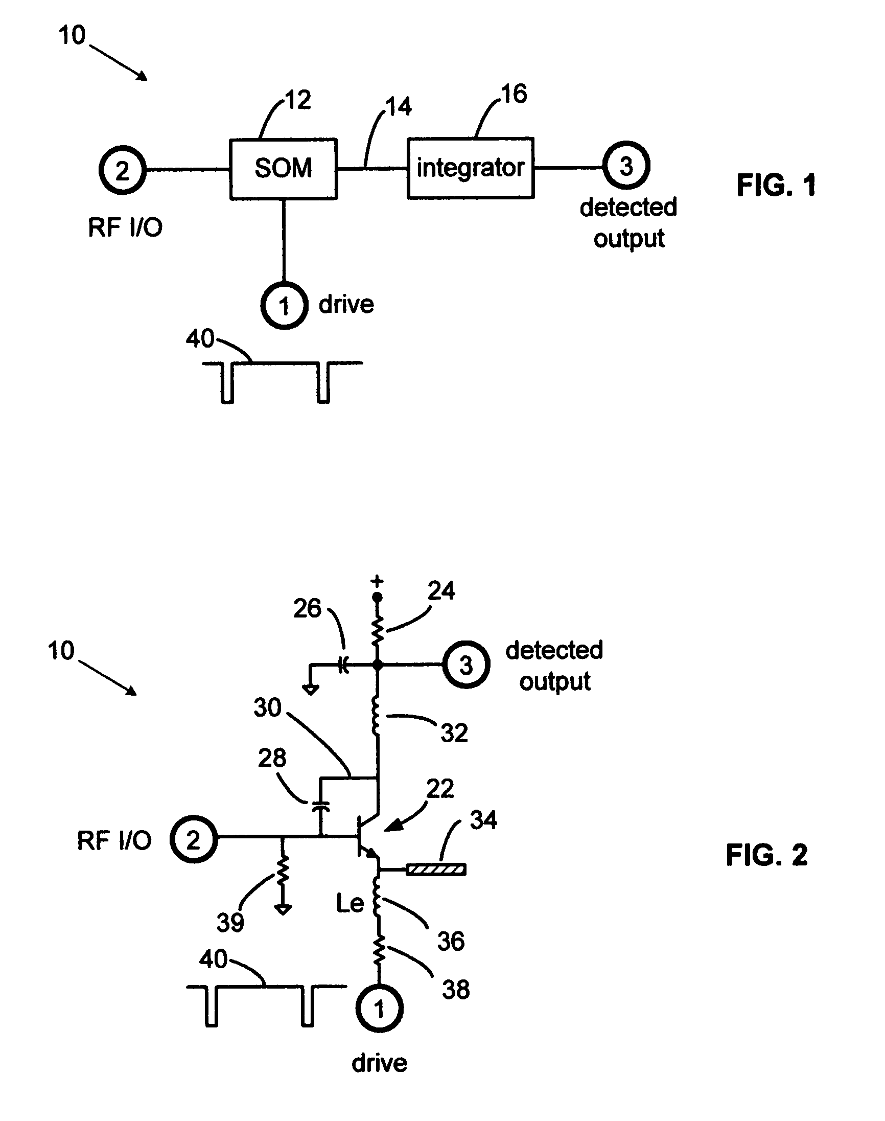
[0025]The present invention overcomes the limitations of the various prior UWB sampling receivers by employing a self-oscillating mixer (SOM) as a matched bandwidth coherent UWB pulse sampler, and by coupling the SOM to an integrator to produce a detected output. The acronym “UWB” is shorthand notation and refers to both a historical definition of ultra-wideband: any signal having a bandwidth of greater than 1 MHz; and to a modern definition of UWB: a signal bandwidth of greater than 25% of its center frequency. Although the claimed apparatus can operate with multi-GHz UWB RF signals, it can also operate with narrowband signals of less than 1 MHz.

[0026]The self-oscillating UWB emitter-detector operates by mi...


PUM


Abstract

A UWB RF detector employs a pulsed self-oscillating mixer (SOM) and an output integrator to provide low-noise preamplification, mixing and sampling. The SOM produces short-burst, microwave self-oscillations that are phase-locked to a clock. The self-oscillations are used for mixing. The SOM can also radiate UWB RF pulses. A one-transistor SOM can simultaneously implement both a UWB emitter and a UWB detector in a radar transceiver. A control loop can stabilize the self-oscillations at nanowatt levels. Nanowatt UWB radars and radios can be realized, thereby opening new spectral bands beyond those formally designated for UWB operation.

Description

BACKGROUND OF THE INVENTION[0001]1. Field of the Invention[0002]The present invention relates to radar detection circuits and more particularly to ultra-wideband (UWB) RF pulse detection circuits. The invention can be used to detect pulses for UWB radar rangefinders, motion sensors, time domain reflectometers (TDR), pulsed laser sensors, radiolocation systems, and communication systems.[0003]2. Description of Related Art[0004]In 1918, Edwin H. Armstrong invented the superheterodyne radio which translated a high incoming radio frequency (RF) to an intermediate frequency (IF) using a local oscillator and a mixer. Shortly thereafter, the mixer and oscillator were combined into a single function using a single vacuum tube which functioned as both a local oscillator and a mixer. A device that functions as both an oscillator and a mixer can be termed a self-oscillating mixer (SOM). The oscillations in early radio SOMs were continuous wave (CW) and were not phase coherent with the incoming...

Claims


Application Information

Patent Timeline
IPC IPC(8): G01S13/00
CPCG01S7/288G01S13/0209H03D1/18H03D7/12
Inventor MCEWAN, THOMAS EDWARD
Owner MCEWAN TECH
Learn More