Valve actuators

a valve actuator and actuator technology, applied in the field of valve actuators, can solve the problems of affecting the efficiency and effectiveness of the valve actuator in normal use, requiring relatively high power consumption, and affecting the stability of the control loop, and achieve the effect of low power consumption and cost effectiv

Active Publication Date: 2012-02-21
ROTORK CONTROLS LTD
View PDF63 Cites 160 Cited by
  • Summary
  • Abstract
  • Description
  • Claims
  • Application Information

AI Technical Summary

Benefits of technology

[0011]By using the two sensors for feedback control and thereby overcoming the stick-slip problems a high level of control accuracy and reliability is achieved while avoiding the need for expensive high grade, low backlash gears. Accordingly, with careful selection of materials and design to get the required life, it is now possible to produce a low cost drive train with an excellent level of accuracy.
[0017]Typically, the first sleeve houses electronic components for pre-conditioning signals received from the or each strain gauge and the signal from the or each strain gauge may be carried along a signal conductor passing through the inside of the output shaft. This provides advantages because cables do not need to be routed outside the actuator via sealing glands or the like and are thus within the protection of the enclosure.
[0019]The switch may, for example, be a Hall or Reed switch. This simplifies the set up task for the user while avoiding risk of sparking from use of an intrusive mechanical device and avoiding the need for the user to have access to a PDA or other wireless control device simply to initiate the set-up. Preferably for safety, the user interface is configured so that on removal of the device from proximity to the switch the start up routine is halted.
[0023]The actuator may include a lateral support arrangement for the linear output shaft in which a support arm or prop is adjustably extendible toward the axis of the shaft proximate that part of the shaft that is acted upon by the pinion / gearing of the drive train to maintain the orientation of the axis of the shaft and prevent backlash. Suitably this arm or prop acts against the rack body.
[0025]This arrangement gives the user a low power consumption, cost effective and fully torque / thrust-controlled arrangement for returning the actuator to the desired failsafe state and effectively allows the user to tailor the failsafe tension to the required level for each installation whereby the valve will re-seat securely without insufficient or excessive force.

Problems solved by technology

This does, however, require use of a relatively high amount of power just to overcome the force of the return spring for normal operation.
A number of factors undermine efficient and effective operation of the valve actuator in normal use and these include gear wear, controller saturation, wind up and overshoot.
The latter factors, that may be referred to as “stick-slip” factors, are commonly encountered with valve actuators and can prove a major impediment to maintaining efficiency in the closed loop processes implemented by control valve actuators, where rapid and often very small adjustments are required to be made to the valve position in order to maintain process control.
To overcome an initial heavy load, the controller will often be driven into saturation and, therefore, wind-up action (where the controller gives full power but the load instantaneously disappears and the controller is still fully powered) which will give rise to the valve overshooting its desired position and causing control loop instability.
This can lead to stick slip problems as when the air pressure is raised or lowered to move the valve by a small amount a sudden change in friction can cause the actuator to jump by more than the desired movement.
They are also subject to unwanted movements due to changes in valve stem force as this unbalances the forces and the actuator needs to alter the air pressure to compensate.
Electric motor driven valve actuators also suffer from stick slip problems although less so than pneumatics.
However they can suffer from poor control due to backlash in the drive train.
This and the long life requirements due to continuous operation make the drive train very expensive.

Method used


Image

  • Valve actuators
  • Valve actuators
  • Valve actuators

Examples


Embodiment Construction

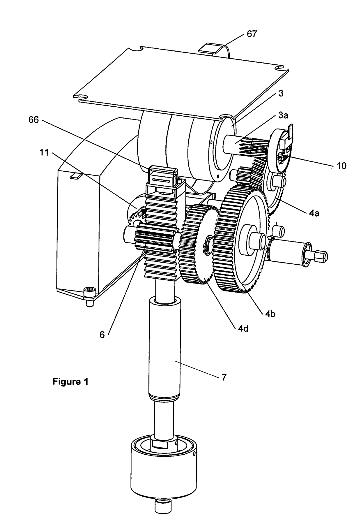
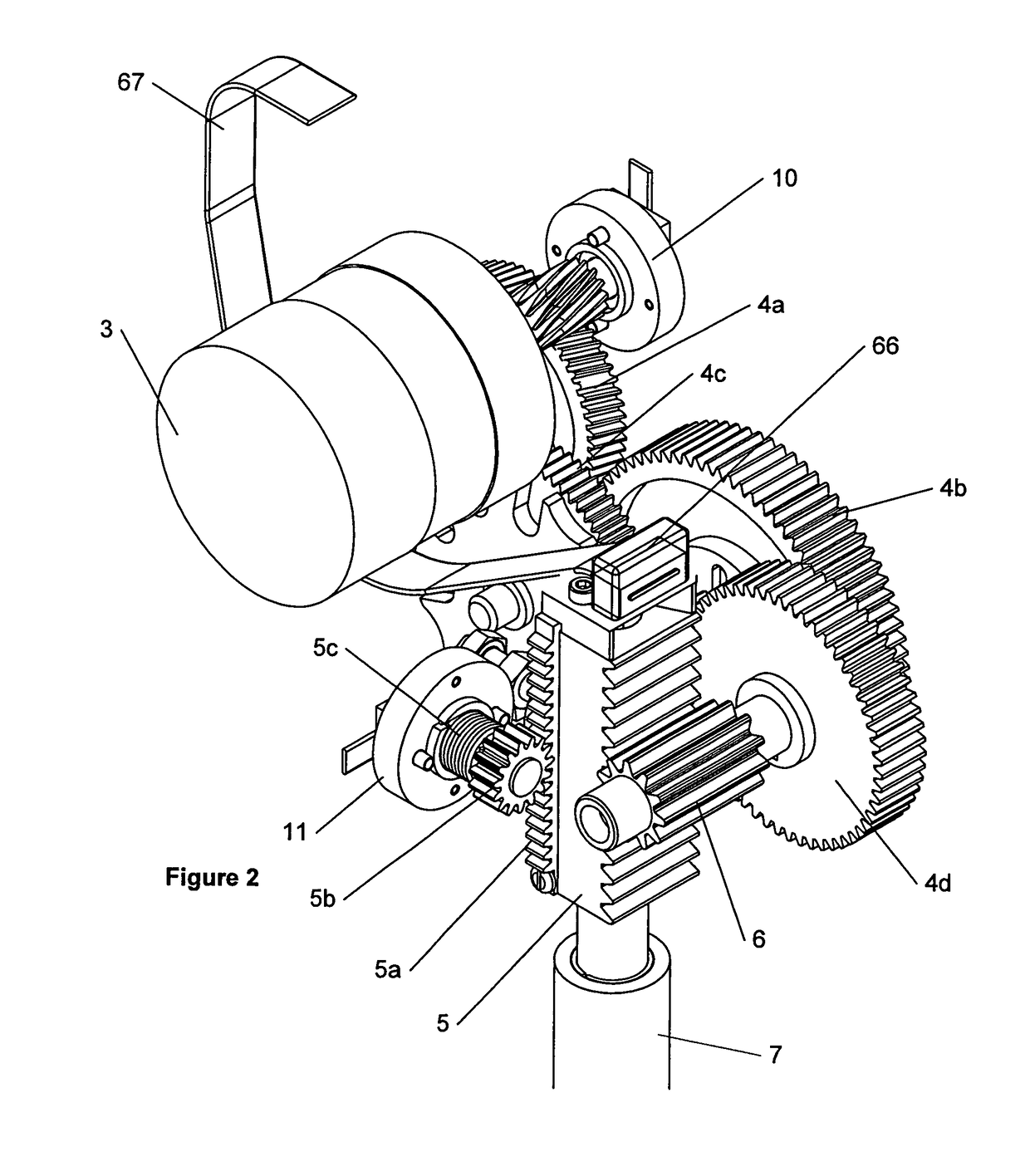
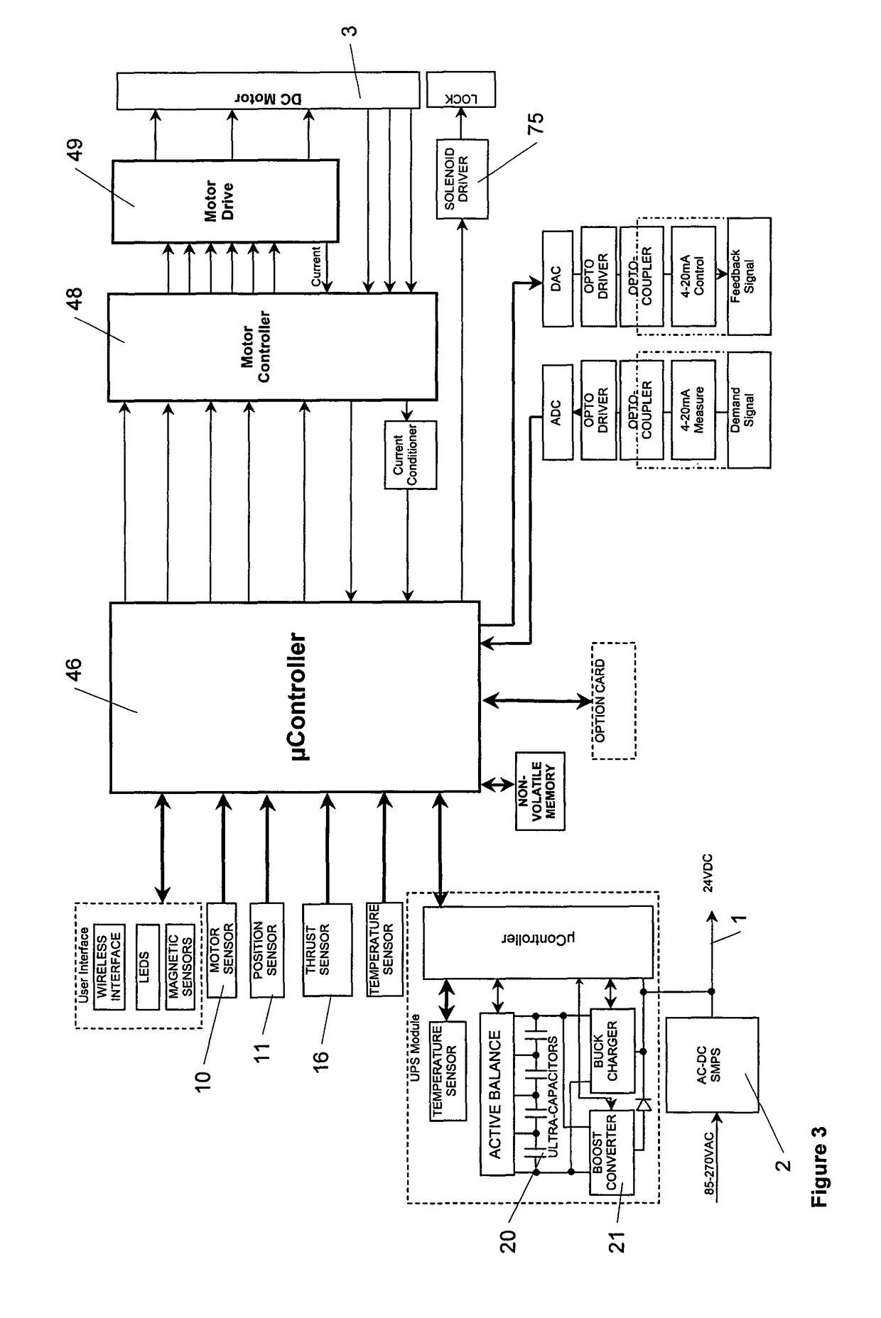
[0039]Referring to FIGS. 1 to 4, the system typically includes a DC power supply 1 provided by a switched mode power supply 2 that generates the voltages required for the electric drive motor 3 and electronics. The drive motor 3 of the actuator suitably comprises a permanent magnet DC motor that drives through a spur gear drive train 4a-d to a rack 5 and pinion 6. The rack 5 is coupled to an output shaft 7 of the actuator that provides the linear output required to vary the extent of opening of the control valve. The control valve is not shown in the figures.

[0040]The electric drive motor 3 is permanently connected to its power supply 1 with the voltage varied by a motor controller 48 and power drive 49 to move the motor 3 and vary its speed and / or torque.

[0041]A first non-contacting digital position sensor 11, that suitably is a rotary / shaft encoder is present adjacent the end of the pinion 6 that drives the actuator output shaft 7 to detect the position of the output shaft 7. The ...


PUM


Abstract

A valve actuator having an electric drive motor with a motor shaft and having an output shaft linked to the motor shaft to drive movement of a valve, the actuator further having a control system arranged to provide a first closed loop control of the actuator output shaft and including a controller coupled to a first position sensor to sense the position of the actuator output shaft, and to a second position sensor to sense the position of the motor shaft and to enable determination of the speed of the motor shaft, the control system being configured to respond to sensed signals from the first and second sensors and adjust the motor speed / position accordingly.

Description

CROSS REFERENCE TO RELATED APPLICATIONS[0001]This application represents the national stage application of International Application PCT / GB2007 / 002531 filed 9 Jul. 2007, which claims the benefit of Great Britain Patent Application 0613662.6 filed 10 Jul. 2006, which are incorporated herein by reference in their entirety for all purposes.FIELD OF THE INVENTION[0002]The present invention concerns improvements in and relating to valve actuators, and is particularly, but not necessarily exclusively, applicable to control valve actuators, being actuators for the control of valves that adjust the flow of fluids in a conduit—commonly, for example, in response to a signal from a process measurement. Such actuators generally need high accuracy and serve to provide continuous coarse and fine adjustment of fluid flow rates in the conduit rather than simply switching flow by completely opening and shutting the conduit.BACKGROUND TO THE INVENTION[0003]Valve actuators find wide application, for e...

Claims


Application Information

Patent Timeline
Patent Type & Authority Patents(United States)
IPC IPC(8): F16K31/02
CPCG05B19/39Y10T137/8242B06B1/00F16K31/04G05B9/02G05D3/12G05D13/64H02J9/06H02P7/00
Inventor SANDERS, PETER GEORGEDASSANAYAKE, HEMENDRA PARAKRAMA BANDARAWITHERS, ANDREW MARK
Owner ROTORK CONTROLS LTD
Why Eureka
Try Eureka