Interlayer film separation method

a technology of interlayer film and separation method, which is applied in the field of interlayer film separation method, can solve the problems of not being economically preferable and not being recyclable, and the interlayer film cannot be collected in a recyclable condition

Inactive Publication Date: 2012-02-21
GLASS TECHNO SYNERGY CO LTD
View PDF13 Cites 51 Cited by
  • Summary
  • Abstract
  • Description
  • Claims
  • Application Information

AI Technical Summary

Problems solved by technology

However, according to the above-mentioned separation method, an interlayer film is swollen and deterioration due to hydrolysis and the like progresses, and therefore, the interlayer film could not be collected in a recyclable condition.
Further, treatment time until the interlayer film and the crushed glass plate can be easily separated is a long period of time as several hours to several days in the above-mentioned separation method, and thus there is a problem that the method is not economically preferable.

Method used


Image

  • Interlayer film separation method
  • Interlayer film separation method

Examples


example 1

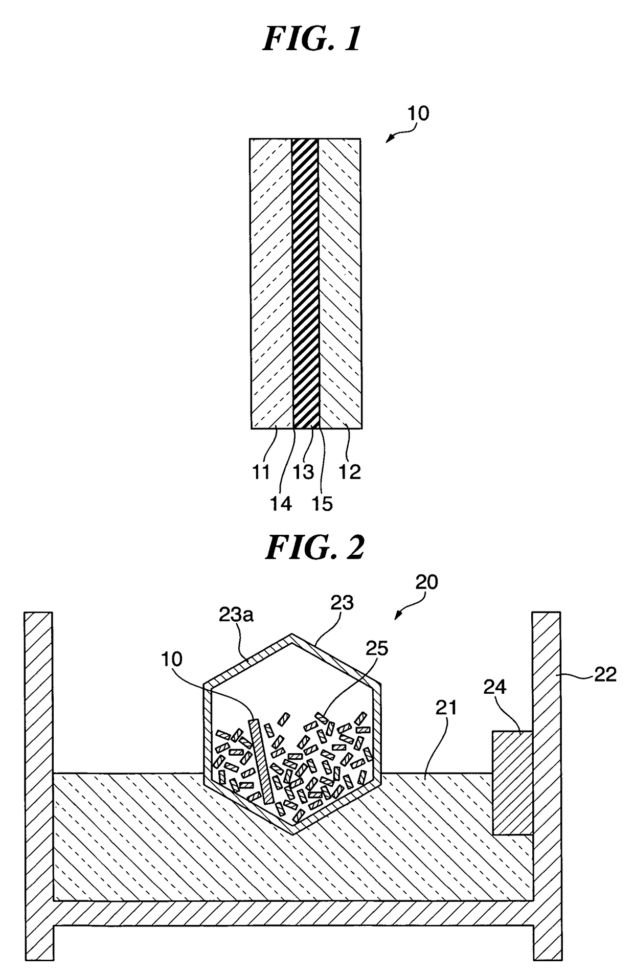
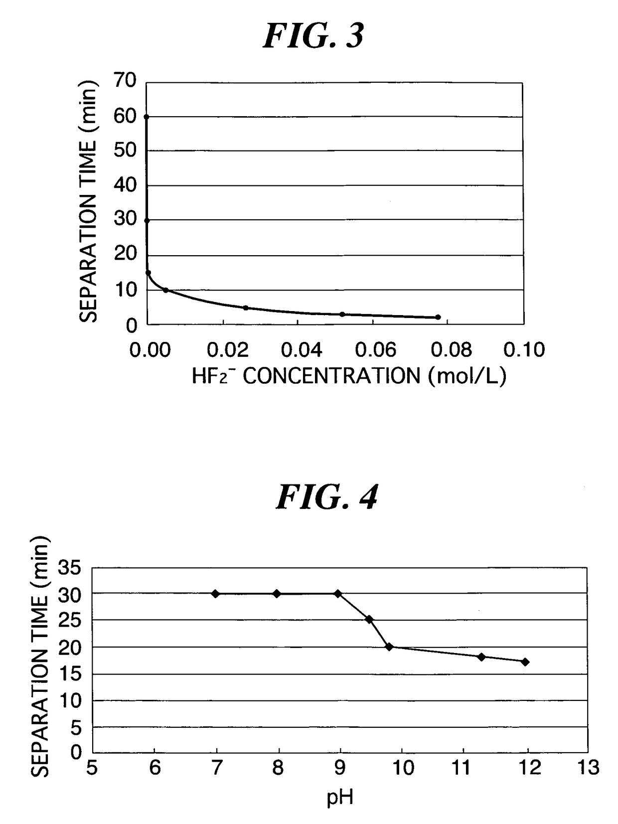
[0057]In Example 1, the interlayer film separation solution 21 was introduced into the container 22, and the introduced interlayer film separation solution 21 was controlled to a temperature of 40° C., and the laminated glass 10 with cracks reaching interfaces 14, 15 in the glass plates 11, 12, respectively, was introduced into the barrel 23 with the metal pieces 25 and immersed in the interlayer film separation solution 21. In this case, six types of treatment liquids (samples 1 to 6) were prepared so that the HF2− concentration were 0 to 0.08 mol / L as the interlayer film separation solution 21. Each of these treatment liquids was obtained by diluting an aqueous solution of about 23 mol / L (46 wt %) hydrofluoric acid with water.

[0058]Concentrations of hydrofluoric acid aqueous solutions, HF2− concentrations, etching rates, and time (separation time) until glass is completely separated from the laminated glass 10 (a weight ratio of a total weight of the glass plates 11, 12 to a total...

example 2

[0063]In Example 2, an interlayer film separation solution 21 was introduced into a container 22, and the introduced interlayer film separation solution 21 was controlled to a temperature of 40° C., and laminated glass 10 with cracks reaching interfaces 14, 15 in glass plates 11, 12, respectively, was introduced into a barrel 23 with metal pieces 25 and immersed in the interlayer film separation solution 21. In this case, 7 types of potassium hydroxide aqueous solutions were prepared as the interlayer film separation solution 21 so that the hydrogen ion concentration (pH) were 7 to 12. Each of these potassium hydroxide aqueous solutions was obtained by dissolving potassium hydroxide in water and adjusting the resulting solution to have a concentration of 0 to 0.1 wt %. FIG. 4 is a graph showing the relationship between a hydrogen ion concentration (pH) and time until a residual rate of glass becomes 0% in an interlayer film separation solution (40° C.) according to the present embod...

example 3

[0065]In Example 3, an interlayer film separation solution 21 was introduced into a container 22, and the introduced interlayer film separation solution 21 was controlled to a temperature of 40° C., and laminated glass 10 with cracks reaching interfaces 14, 15 in glass plates 11, 12, respectively, was introduced into a barrel 23 with metal pieces 25 and immersed in the interlayer film separation solution 21. In this case, an acidic aqueous solution containing hydrofluoric acid (HF2− concentration: 0.005 mol / L) and a surfactant (0.5 wt %), and having a hydrogen ion concentration (pH) of 1.9 was used as the interlayer film separation solution 21. An etching rate and a surface tension of this acidic aqueous solution were 30 nm / min and 35 N / m, respectively. In addition, time until a residual rate of glass becomes 0% was 9 minutes. It was found from the comparison with the time until a residual rate of glass becomes 0% (10 minutes) when the laminated glass 10 was immersed in Sample 3 in ...


PUM

PropertyMeasurementUnit
temperatureaaaaaaaaaa
sizeaaaaaaaaaa
surface tensionaaaaaaaaaa

Abstract

There are provided an interlayer film separation solution and an interlayer film separation method capable of separating an interlayer film and a glass for a short period of time and collecting the separated interlayer film in a recyclable condition. An interlayer film separation solution 21 having etching ability for a glass is introduced into a container 22, and the introduced interlayer film separation solution 21 was controlled to a temperature of 30 to 60° C., and a laminated glass 10 with glass plates 11, 12 crushed is introduced into a barrel 23 from a lid portion 23a, and simultaneously, 50 to 60 metal pieces 25 are, introduced into the barrel 23 from the lid portion 23a in order to easily separate the laminated glass 10 into the glass plates 11, 12 and an interlayer film 13. The barrel 23 containing the laminated glass 10 and the metal pieces 25 introduced thereinto is rotated at a predetermined rotational speed.

Description

[0001]This application is a U.S. National Phase Application under 35 USC 371 of International Application PCT / JP2006 / 318437 filed Sep. 11, 2006.TECHNICAL FIELD[0002]The present invention relates to an interlayer film separation method for separating an interlayer film and glass plates interposing the interlayer film therebetween. The present invention particularly relates to an interlayer film separation method useful for recycling of interlayer films.BACKGROUND ART[0003]As a conventional method for recycling a laminated glass, there is a method in which a glass plate in the laminated glass is crushed and this crushed glass plate is immersed in water or water containing a surfactant for several hours to several days, and thereby an interlayer film is swollen to reduce adhesive strength between the interlayer film and the glass plate, thereby separating the interlayer film and the glass plate (see, for example, Japanese Patent Application Laid-Open No. 6-247752).[0004]However, accord...

Claims


Application Information

Patent Timeline
Patent Type & Authority Patents(United States)
IPC IPC(8): B32B38/10
CPCB29B17/02B32B17/10761B32B17/10788B32B17/1099B32B43/006C03C15/00C03C23/0075C08J11/08B29B17/0412Y10T156/1153B29B2017/0293B29B2017/0296B29K2031/04B29K2709/08B29L2031/7782B32B2309/02B32B2309/04B32B2315/08Y10S156/927Y10T156/1116Y10T156/1922Y10T156/1121Y10T156/1111Y10T156/1142Y02W30/62
Inventor HORI, MASAHIROMITANI, KAZUISHISAITO, YASUHIROTAKATSUKI, NOBUYUKISHUKURI, KYOUICHIKURAMOTO, SHUNJI
Owner GLASS TECHNO SYNERGY CO LTD
Why Eureka
Try Eureka