Power transducer

a technology of power transducer and power semiconductor, which is applied in the direction of motor/generator/converter stopper, dynamo-electric converter control, ac motor stopper, etc., can solve the problems of thermal destruction and deactivation, and achieve the effect of improving the performance of the power transducer and efficiently using the power semiconductor

Active Publication Date: 2012-02-21
HITACHI IND EQUIP SYST CO LTD
View PDF15 Cites 6 Cited by
  • Summary
  • Abstract
  • Description
  • Claims
  • Application Information

AI Technical Summary

Benefits of technology

[0015]An object of the present invention is to improve the performance of the power transducer while efficiently using the power semiconductor also by managing the permissible duty factor % ED of the power semiconductor in the regenerative braking circuit provided in the power transducer.
[0026]In accordance with the present invention, it becomes possible to manage the permissible duty factor % ED of the power semiconductor in the regenerative braking circuit provided in the power transducer, thus improving the performance of the power transducer while efficiently using the power semiconductor in the regenerative braking circuit.

Problems solved by technology

Therefore, the power semiconductor generates heat because of loss electrically generated during electric power conversion and, operating the power transducer beyond the semiconductor's operating limit temperature may result in thermal destruction and deactivation.

Method used


Image

  • Power transducer
  • Power transducer
  • Power transducer

Examples


first embodiment

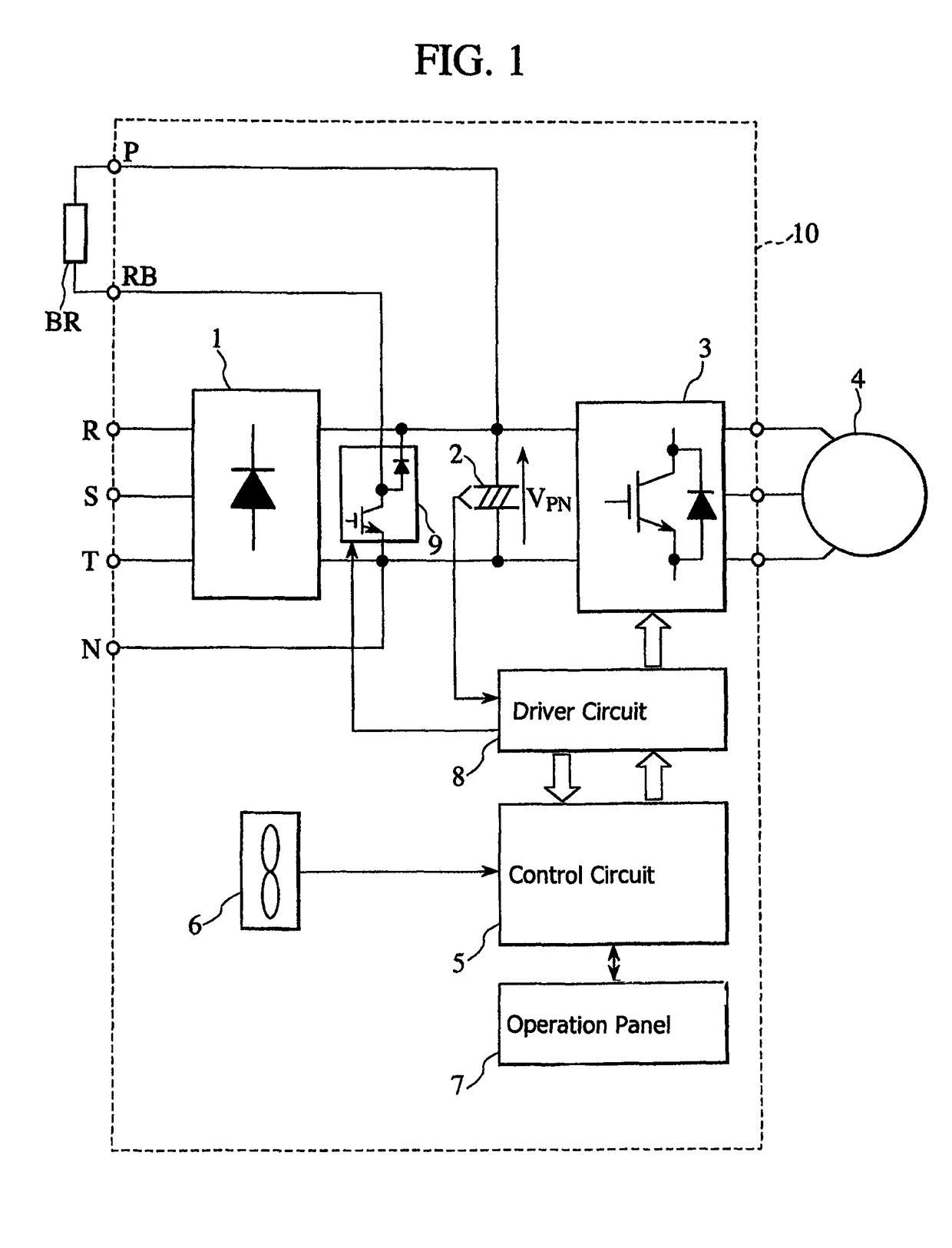
[0034]FIG. 1 is a schematic view showing the circuit configuration of a power transducer according to the present embodiment. The power transducer 10 includes: a converter 1 which converts AC power to DC power; a smoothing capacitor 2 located in the DC intermediate circuit of the power transducer 10; an inverter 3 which inverts DC power to AC power at an arbitrary frequency; and an AC motor 4.

[0035]The power transducer 10 further includes: a cooling fan 6 which cools the converter and a power module in the inverter; and a digital operation panel 7 used to set and change various control data of the power transducer, and display and monitor abnormal states.

[0036]The power transducer 10 further includes a control circuit 5 which includes a microcomputer (control and calculation unit) to control a switching element of the inverter and at the same time performs total control of the power transducer, thus allowing required control processing based on various control data input through the...


PUM


Abstract

The performance of a power transducer is improved while efficiently using a power semiconductor also by managing the permissible duty factor of the power semiconductor in the regenerative braking circuit provided in the power transducer. The user is allowed to set, through an operation panel provided on the power transducer, the resistance value of the regenerative braking resistor for thermally consuming the rotational energy generated during motor deceleration. The power transducer performs the steps of: calculating the current which flows in the regenerative braking circuit from the resistance value setting; obtaining the generation loss of the power semiconductor in the regenerative braking circuit with the calculated current value; and determining the permissible duty factor of the power semiconductor from the obtained generation loss.

Description

CLAIM OF PRIORITY[0001]The present application claims priority from Japanese application serial no. JP2008-058918, filed on Mar. 10, 2008, the content of which is hereby incorporated by reference into this application.BACKGROUND OF THE INVENTION[0002]1. Field of the Invention[0003]The present invention relates to a power transducer.[0004]2. Description of the Related Art[0005]Inverters, a form of electrical power transducer, have been widely adopted in industries and also used in household electric appliances as rotational velocity control devices for AC motors. When the rotor of an AC motor is decelerated, the rotational energy of the AC motor during the deceleration is accumulated as electrostatic energy in a smoothing capacitor located in the DC intermediate circuit of its transducer. However, voltages may increase at both ends of the smoothing capacitor due to its small capacitance. This puts into operation the overvoltage protection circuit provided in the DC intermediate circu...

Claims


Application Information

Patent Timeline
Patent Type & Authority Patents(United States)
IPC IPC(8): H02P3/00
CPCH02M5/458H02M1/32H02P3/14H02P3/22
Inventor IBORI, SATOSHIUCHINO, YOSHIHIROWATANABE, HIROSHIHIRAGA, MASAHIRO
Owner HITACHI IND EQUIP SYST CO LTD
Why Eureka
Try Eureka