Multi-stage power amplifier with enhanced efficiency

a multi-stage, power amplifier technology, applied in amplifiers, amplifiers with semiconductor devices only, amplifiers with semiconductor devices, etc., can solve the problems of reducing the efficiency of amplifiers, limiting output power, and limiting the efficiency of wireless communication devices, so as to and improve the efficiency of signal amplification

Active Publication Date: 2012-03-06
SKYWORKS SOLUTIONS INC
View PDF3 Cites 22 Cited by
  • Summary
  • Abstract
  • Description
  • Claims
  • Application Information

AI Technical Summary

Benefits of technology

[0012]In accordance with a preferred embodiment, the multi-stage power amplifier of the present invention is capable of efficient signal amplification in multiple operating modes. In one operating mode, the first amplifying stage (high power) is enabled while the second amplifying stage (low power) is disabled. The secondary impedance matching network is switched out and has no impact on the impedance of the primary matching network. The resulting output impedance sets the output power of the active stage to its peak value, thereby improving its efficiency. In another operating mode, the first amplifying stage is disabled and the second amplifying stage is enabled. The secondary impedance matching network is presented between the amplifying stages and the primary impedance matching network, thereby raising the impedance of the primary matching network. The resulting output impedance sets the output power of the active stage to its peak value, thereby improving its efficiency.

Problems solved by technology

Variable-envelope modulation schemes, such as CDMA (Code Division Multiple Access), for example, typically limit output power because of signal distortion occurring at high output power levels and are usually referred to as linear applications, i.e. requiring the employment of a linear amplifier.
The efficiency of a wireless communication device is primarily limited by the efficiency of the device's power amplifier because it imposes the largest drain on the battery.
For maximum efficiency, power amplifiers are generally designed to operate at their peak output power, and any deviation from the peak output power reduces the amplifier's efficiency.
A problem with such parallel-stage design is that each amplifying stage can adversely affect the performance of the other.
In one aspect, the impedance matching network of the disabled stage may alter the effective impedance of the active stage and reduce its efficiency.
In another aspect, the output impedance of an amplifying transistor may vary during operation adversely affecting that of the other transistor.
These conditions may cause cross-coupling and power leakage between the stages, so that each stage operates less efficiently than intended.
Designs based on quarter-wavelength transformers, such as that of Stengel et al., are too bulky for the compact and inexpensive personal wireless communication devices favored by consumers.
It thus consumes a large space in the device if implemented as part of the integrated circuit and requires a large area on the integrated circuit, unduly increasing its size and cost.
In another aspect, a quarter-wavelength transformer has a relatively limited frequency response that is too inflexible for communication devices operating in multiple frequency bands.
Switches, however, can also be physically large and impractical unless integrated on the same IC as the power amplifier.

Method used


Image

  • Multi-stage power amplifier with enhanced efficiency
  • Multi-stage power amplifier with enhanced efficiency
  • Multi-stage power amplifier with enhanced efficiency

Examples


Embodiment Construction

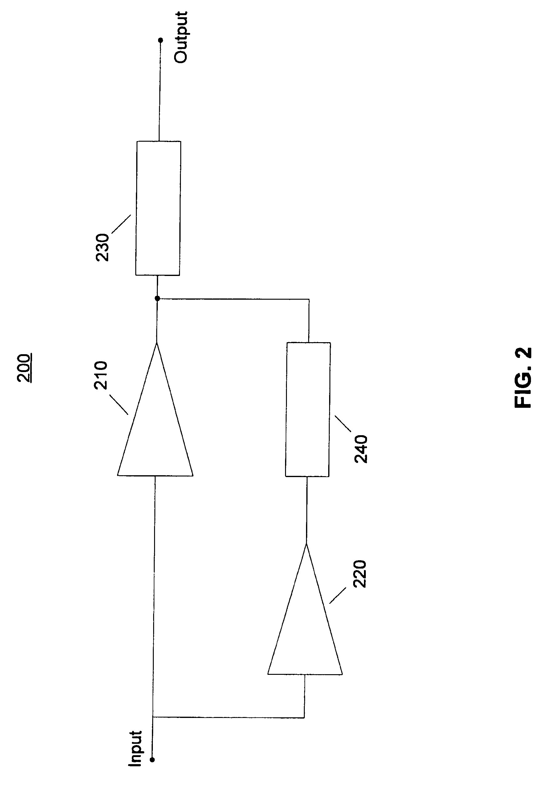
[0025]A block diagram of an RF / Microwave multi-stage power amplifier in accordance with a preferred embodiment of the invention is shown in FIG. 2. Power amplifier 200 comprises two amplifying stages 210 and 220, an output matching network 230, connected to the output of the first amplifying stage, and an output pre-matching network 240, connected between the outputs of amplifying stages 210 and 220. Power amplifier 200 further comprises power control circuits (not shown) connected to amplifying stages 210 and 220 that are capable of enabling or disabling each stage. By means of this circuit topology, amplifying stage 210 may be presented with a first predetermined output impedance suitable for its efficient operation, while amplifying stage 220 may be presented with a second output impedance suitable for its efficient operation.

[0026]In a preferred embodiment, amplifying stage 210 has a greater power capacity than amplifying stage 220, which enables power amplifier 200 to operate i...


PUM


Abstract

A multi-stage RF / Microwave power amplifier circuit is provided that is capable of operating efficiently at multiple output power levels. The amplifier comprises first and second amplifying stages, an output impedance matching network connected to the output of first amplifying stage and an interstage impedance matching network connected between the outputs of said first and second amplifying stages. In a high power mode, the first amplifying stage is enabled and the second amplifying stage is disabled and the output and interstage impedance matching networks present a first value of the output impedance that improves the efficiency of the first amplifying stage. In a low power mode, the first amplifying stage is disabled and the second amplifying stage is enabled, and output and interstage impedance matching networks present a second value of the output impedance that improves the efficiency of the second amplifying stage.

Description

CROSS-REFERENCE TO RELATED APPLICATIONS[0001]The present application is a continuation of application Ser. No. 10 / 949,509 filed Sep. 24, 2004 now abandoned which claims priority benefit under 35 U.S.C. §119 of prior filed U.S. provisional application Ser. No. 60 / 505,930, filed Sep. 25, 2003, which is incorporated herein by reference in its entirety.BACKGROUND OF THE INVENTION[0002]The present invention relates to the field of power amplifiers. More particularly, it relates to a multi-stage radio-frequency (“RF”) power amplifier having a single input port and a single output port with two or more modes of operation at different power level ranges. Each mode has its active output stage presented with a near optimum load impedance to provide an improved trade off between efficiency and linearity.[0003]Personal wireless communication devices are often required to operate at multiple output power levels to maintain their efficiency (i.e., the ratio of signal output power to the total inp...

Claims


Application Information

Patent Timeline
Patent Type & Authority Patents(United States)
IPC IPC(8): H03F3/68
CPCH03F1/0277H03F3/189H04B2001/045H03F1/02H03F3/24
Inventor ARELL, THOMAS W.
Owner SKYWORKS SOLUTIONS INC
Why Eureka
Try Eureka