

Wireless microphone device
a microphone and wireless technology, applied in the direction of transducer casings/cabinets/supports, resonant antennas, electrical transducers, etc., can solve the problems of reducing sensitivity, and affecting the operation of the device. , to achieve the effect of reducing the siz
- Summary
- Abstract
- Description
- Claims
- Application Information
AI Technical Summary
Benefits of technology
Problems solved by technology
Method used
Image

Examples
first embodiment
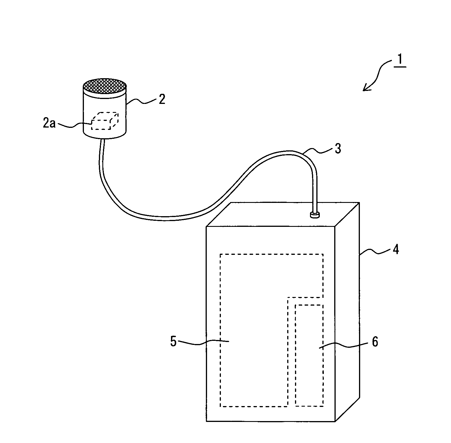
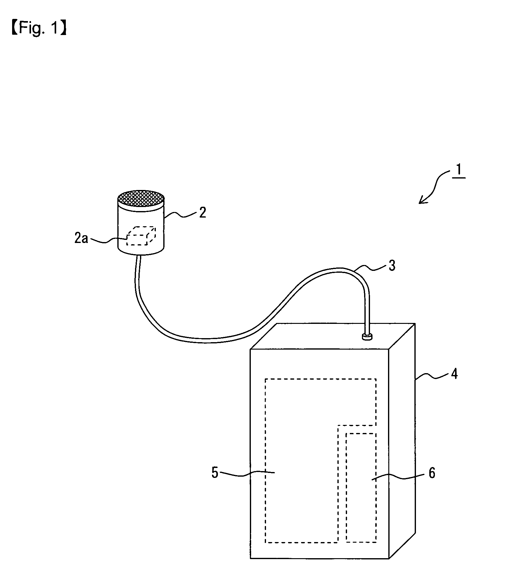
[0023]FIG. 1 is a perspective view illustrating an example of a schematic configuration of a wireless microphone device according to a first embodiment of the present invention, in which a two-piece type microphone device 1 is illustrated. The microphone device 1 includes a microphone unit 2, a transmission cable 3, and a transmitter unit 4, and respective housings of the microphone unit 2 and the transmitter unit 4 are connected to each other through the flexible transmission cable 3.
[0024]The microphone unit 2 is a sound collecting part having a microphone 2a in the housing. The microphone 2a is a sound collecting element for converting voice inputted from outside into an electrical signal to generate a voice signal. We here assume that a finely metal-meshed wind screen is arranged on one end face of the cylindrical housing, and the voice is inputted to the microphone 2a through the wind screen. Also, we assume that the transmission cable 3 is connected to the other end face. The ...
second embodiment
[0079]In the first embodiment, there is described as an example the case where the connections between the terminal electrodes and the circuit areas are isolated in terms of high frequency by the high frequency isolation elements. In such a case, there exists the problem that the one ends or the parts of the wiring pattern 33 are coupled with the electrically conductive layers 11 in terms of high frequency in the arrangement areas A6 in which the one ends of the terminal electrodes 15a and 15b are arranged. In the present embodiment, by improving the configuration around the terminal electrodes 16a and 15b, the high frequency coupling between the one ends or parts of the wiring pattern 33 and the electrically conductive layers 11 in the above-described arrangement areas for the one ends is prevented.
[0080]FIG. 12 is a cross-sectional view illustrating a configuration example of a wireless microphone device 40 according to a second embodiment of the present invention. The wireless mi...
embodiment 3
[0088]In the present embodiment, there is described a case where in order to suppress currents from being electromagnetically cancelled each other between circuit boards, which may occur when the circuit boards have the multistep structure, the respective circuit boards are electrically connected to each other in a location where two circuit areas face to each other.
[0089]FIG. 15 is an appearance diagram illustrating a schematic configuration of a wireless microphone device according to a third embodiment of the present invention, in which a handheld type microphone device 60 is illustrated. The microphone device 60 includes a wind screen 61 for containing a microphone 63, and a transmitter main body 62. The wind screen 61 is a wind shield formed of a finely metal-meshed net or the like, and prevents the microphone 63 from picking up noise due to wind.
[0090]The transmitter main body 62 is formed of a vertically long tubular housing, and inside the housing, a circuit board 65 provide...
PUM
 Abstract
Description
Claims
Application Information