
Ultrasonic welding device, and packaging machine with an ultrasonic welding device

a welding device and ultrasonic welding technology, which is applied in the direction of press rams, manufacturing tools, other domestic articles, etc., can solve the problems of inability to meet the requirements of production, and inability to produce at a lower cost, so as to achieve the effect of ensuring the constant width of the working gap, and reducing the cost of production

Active Publication Date: 2012-04-17
SYNTEGON TECHNOLOGY GMBH
View PDF7 Cites 7 Cited by
  • Summary
  • Abstract
  • Description
  • Claims
  • Application Information

AI Technical Summary

Benefits of technology

The ultrasonic welding device described in this patent has several technical advantages over previous devices. It is simpler and less expensive to produce, and it ensures a constant width of the working gap, resulting in better welding quality. The device can safely weld plastic films and metal-coated films, and it includes an adjusting device and a regulating device for precise control of the gap width. The anvil is prestressed and can be easily moved, and the device includes two spacing sensors for measuring the gap width. The actuator of the adjusting device is a linear actuator, which is simple and inexpensive. The device can be used for welding different materials, such as plastic film and metal-coated film. Overall, the ultrasonic welding device described in this patent provides a more efficient and effective solution for welding various materials.

Problems solved by technology

An overly narrow working gap, however, typically worsens the material processing and can lead to damage to the films to be welded and the anvil.
If the gap is too wide, an unacceptable weld seam quality is the result.
However, this known device is very complex in its construction and expensive to produce.
Moreover, this device requires a large amount of space, so that its use in packaging machines in particular necessitates a large amount of installation space for the machine.

Method used


Image

  • Ultrasonic welding device, and packaging machine with an ultrasonic welding device
  • Ultrasonic welding device, and packaging machine with an ultrasonic welding device

Examples


Embodiment Construction

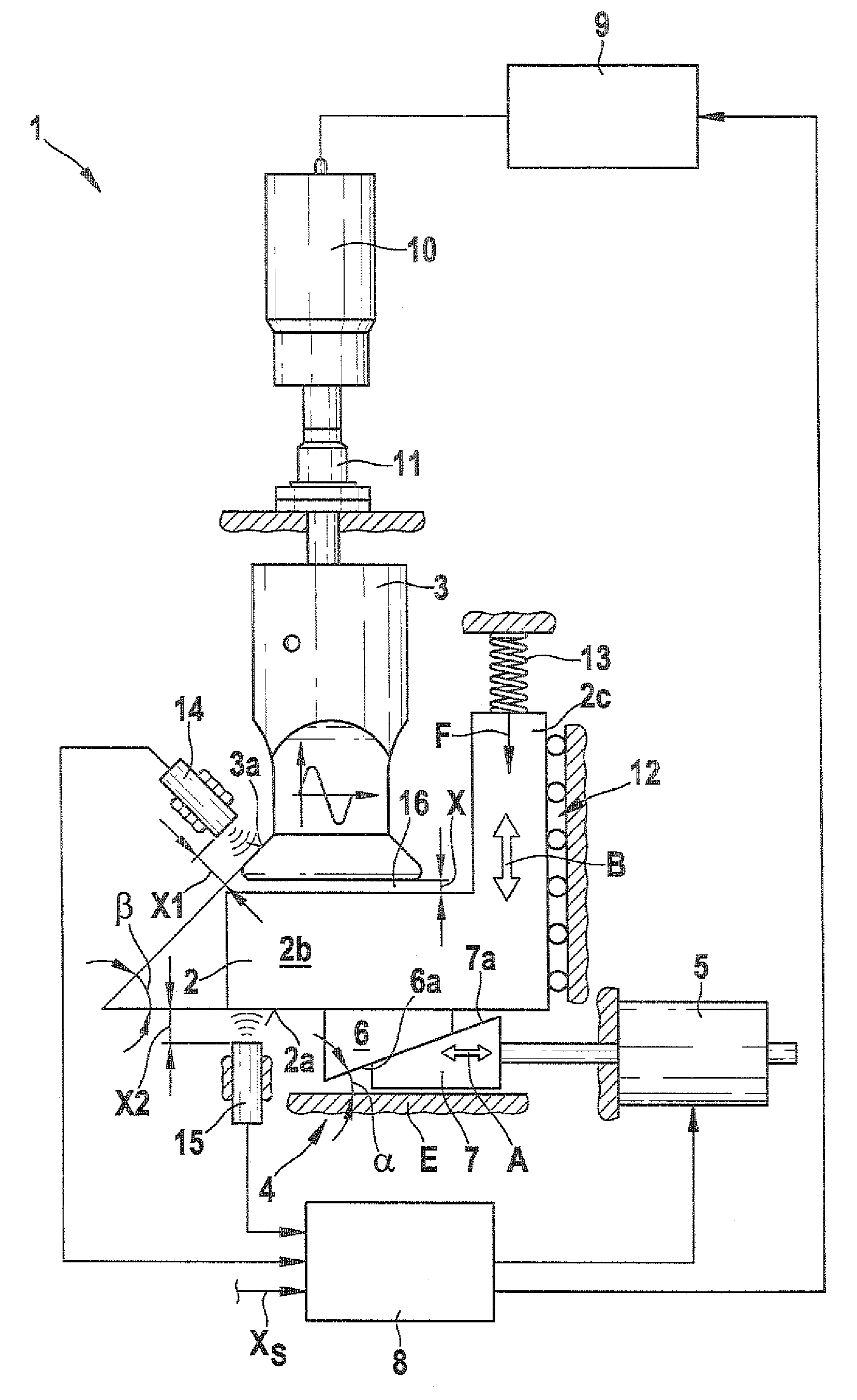
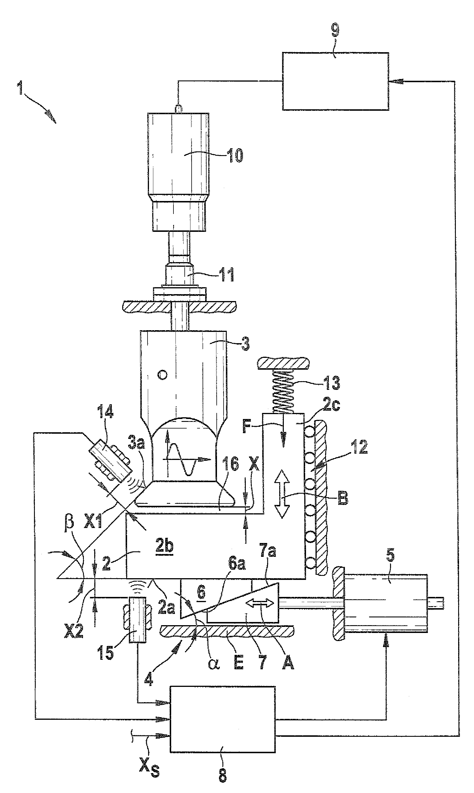
[0018]Below, in conjunction with FIG. 1, an ultrasonic welding device 1 in accordance with an exemplary embodiment of the invention will be described in detail.

[0019]As can be seen from the drawing FIGURE, the ultrasonic welding device 1 includes an anvil 2 and an ultrasonic sonotrode 3. The ultrasonic sonotrode 3 is part of an ultrasound device that includes a generator 9, a converter 10, and an amplitude transformer 11. The amplitude transformer 11 has the function of a booster for the ultrasonic sonotrode 3. Between the anvil 2 and the ultrasonic sonotrode 3, a working gap 16 with a width X is provided. The films to be welded are passed at a constant speed between the ultrasonic sonotrode 3 and the anvil 2 and are welded together by means of the energy input of the ultrasonic sonotrode 3.

[0020]The ultrasonic welding device 1 further includes an adjusting device 4, a regulating device 8, a first spacing sensor 14, and a second spacing sensor 15. As can be seen from the drawing FIG...


PUM

PropertyMeasurementUnit
angleaaaaaaaaaa
angleaaaaaaaaaa
angleaaaaaaaaaa

Abstract

The invention relates to an ultrasonic welding device for welding foil-like materials and includes an ultrasound sonotrode, an anvil, an adjusting unit for adjusting a relative position between the ultrasound sonotrode and the anvil, and a regulating unit which regulates, via the adjustment unit, a width of a working gap between the ultrasound sonotrode and the anvil. The anvil is mounted to be movable with respect to the ultrasound sonotrode on a movable mounting. The adjusting unit has a first wedge element connected to the anvil, a second wedge element, and an actuator. The actuator is connected to the second wedge element, and the second wedge element moves relative to the first wedge element to execute a position change of the anvil relative to the ultrasound sonotrode.

Description

CROSS-REFERENCE TO RELATED APPLICATION[0001]This application is a 35 USC 371 application of PCT / EP 2007 / 059322 filed on Sep. 6, 2007.BACKGROUND OF THE INVENTION[0002]1. Field of the Invention[0003]The present invention relates to an ultrasonic welding device for welding films and in particular for welding longitudinal and / or transverse seams of bag packages, as well as to a packaging machine having such an ultrasonic welding device.[0004]2. Description of the Prior Art[0005]From the prior art, ultrasonic welding devices are known, particularly for welding plastic films. The ultrasonic welding devices typically include an ultrasonic sonotrode and an anvil, and a working gap is formed between the ultrasonic sonotrode and the anvil and the films to be welded are passed through it. A constant working gap between the ultrasonic sonotrode and the anvil is decisive for the quality of the welded seam. Because of the heat produced for instance in processing, the dimensions of the components ...

Claims


Application Information

Patent Timeline
Patent Type & Authority Patents(United States)
IPC IPC(8): B32B37/00B65B9/20
CPCB29C65/08B29C66/712B29C66/82261B29C66/92311B29C66/92611B65B9/20B65B51/225B29C66/1122B29C66/961B29C66/4312B29C66/43B29C66/8242B29C66/849B29L2009/003B29L2031/7128B29C66/72321B29C65/00B29C66/8227B29C66/8322B29C66/836B29C66/92613
Inventor WIEDUWILT, ULRICHLOECHT, HEINRICH
Owner SYNTEGON TECHNOLOGY GMBH
Learn More