Digital control switching power supply unit

a power supply unit and digital control technology, applied in pulse manipulation, pulse technique, instruments, etc., can solve the problems of feedback control taking longer, delay time td of delay elements dcell also fluctuating, transient response characteristics, etc., to achieve simple circuit configuration and control methods, the effect of improving the transient response characteristics

Active Publication Date: 2012-04-24
FUJI ELECTRIC CO LTD
View PDF19 Cites 13 Cited by
  • Summary
  • Abstract
  • Description
  • Claims
  • Application Information

AI Technical Summary

Benefits of technology

[0032]With the digital control switching power supply unit according to the invention, as the A / D converter circuit carries out a conversion operation in synchronization with the switching cycle, an advantage is achieved in that the transient response characteristics are improved with a simple circuit configuration and control method.

Problems solved by technology

Also, the delay time td of the delay elements Dcell also fluctuates due to the effect of a variation in element size or a parasitic device.
With the digital control switching power supply unit, as a digital signal processing such as a PID (Proportional, Integral and Derivative) calculation is necessary, a feedback control takes longer than with an analog control method, and it is known that there is a problem with transient response characteristics.
As the temporal margin is the delay time until an A / D conversion result is reflected in the PWM signal, the kind of excessive margin time shown in B of FIG. 16 delays feedback to the output of an A / D conversion result, and the transient response characteristics of the switching power supply unit are worsened considerably.
The following kinds of problem exist with the heretofore described heretofore known digital control switching power supply units.
Firstly, with the first exemplary configuration example shown in FIG. 13, there is a problem in that there occurs a delay time until the digital error signal e(n), which is the error voltage between the output voltage Vout and reference voltage Vref, is A / D converted by the delay line ADC, and the digital error signal e (n) controls the output voltage Vout via the PWM signal.
Thus, the transient response characteristics of the output are worsened.
However, there is a problem in that a dedicated detector circuit or circuit parts are newly necessary at a time of a sudden load change, and the circuit scale becomes enormous.
Also, there is a problem in that signal controls of an operation at a normal time and an operation at a time of a sudden load change become complicated, and furthermore, it is necessary to individually set a sudden load change detection voltage and the voltage range Vref±Δ, which forms a reference, in accordance with the specifications of the switching power supply unit.

Method used


Image

  • Digital control switching power supply unit
  • Digital control switching power supply unit
  • Digital control switching power supply unit

Examples


first embodiment

[0050]Hereafter, a description will be given, while referring to the drawings, of a digital control switching power supply unit according to an embodiment of the invention.

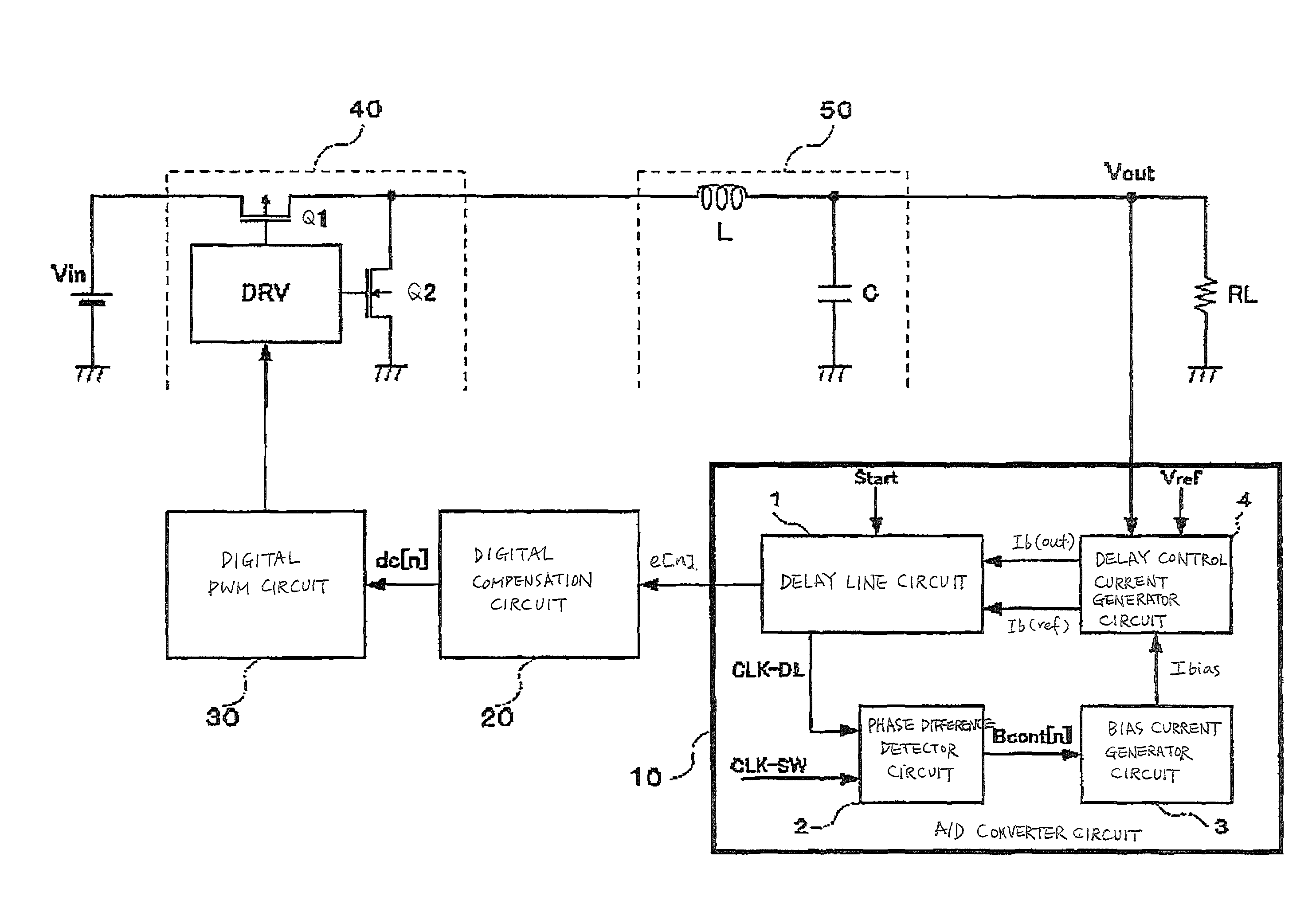
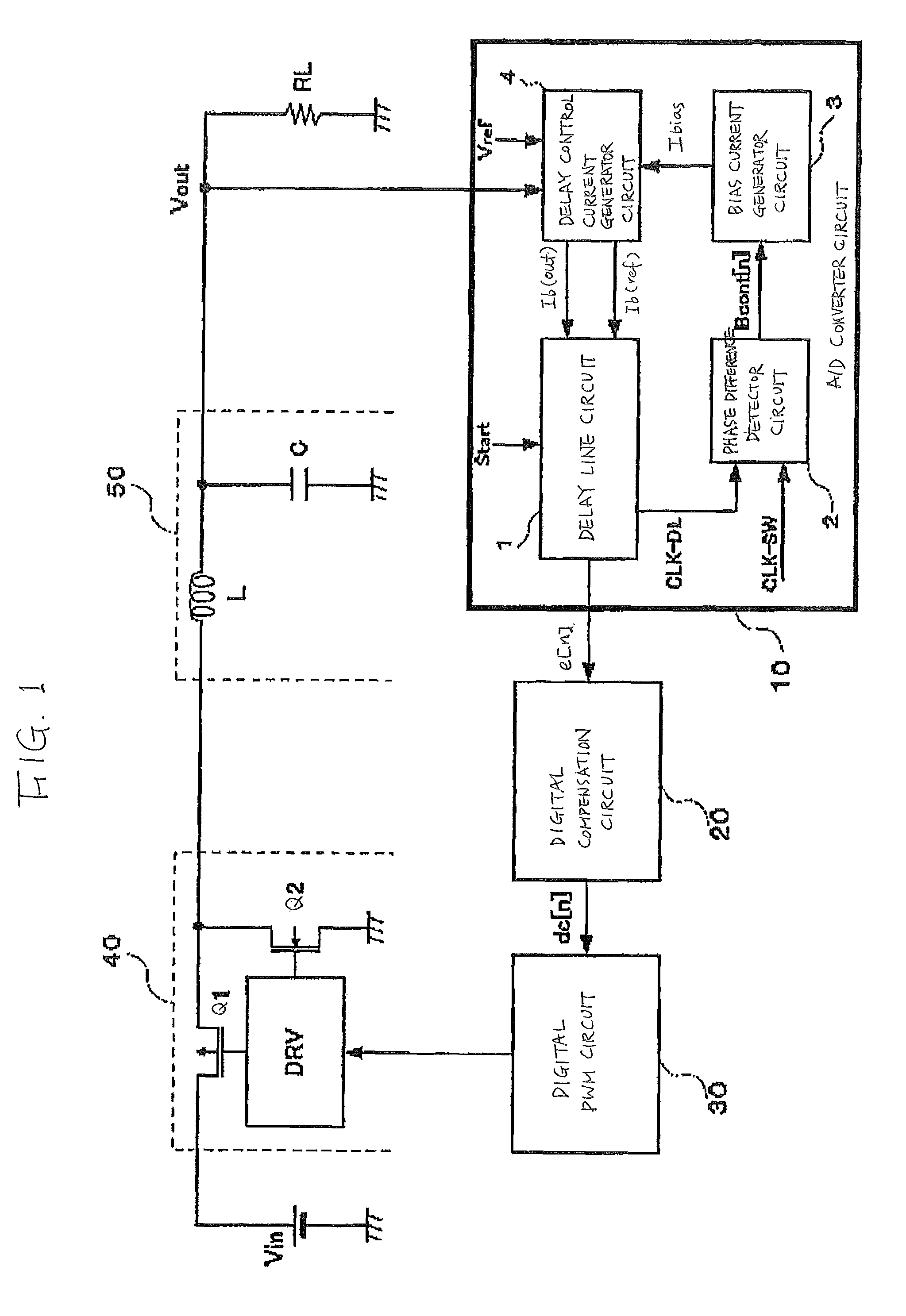
[0051]FIG. 1 is a block diagram showing an exemplary configuration example of the digital control switching power supply unit according to the invention. The same reference numerals and characters are given to places which are the same as in first and second examples of heretofore known digital control switching power supply units shown in FIGS. 13 and 17, and a detailed description will be omitted.

[0052]The digital control switching power supply unit shown in FIG. 1, is an example of a voltage mode, in which a switching element is controlled by a PWM signal and an input voltage Vin is converted to an output voltage Vout. The unit is configured of an A / D converter circuit 10, a digital compensation circuit 20, a digital PWM circuit 30, a switching circuit 40, and an LC smoothing filter 50. As an operation of the d...


PUM


Abstract

A digital control switching power supply unit converts an input voltage into a desired output voltage using a digitally controlled pulse width modulation (PWM) signal according to a switching cycle. The power supply unit includes an analog-to-digital converter (ADC). The ADC converts a result of a comparison between an output voltage and a reference voltage to a digital signal during a conversion cycle. The ADC includes a circuit for outputting a phase difference between a switching cycle and the conversion cycle, and a delay circuit. The delay circuit generates a delay output current based on a result of the comparison and the phase difference and determines the conversion time delay according to the delay output current. The delay circuit also generates a delay reference current based on the reference voltage and the phase difference and determining the duration of the conversion cycle according to the delay reference current.

Description

CROSS-REFERENCE TO RELATED APPLICATION[0001]This application claims priority under 35 U.S.C. §119 from Japanese Patent Application 2009-212103, filed Sep. 14, 2009, the entirety of which is incorporated herein by reference.BACKGROUND OF THE INVENTION[0002]1. Technical Field[0003]The present invention relates to a switching power supply unit that performs a voltage conversion by carrying out a switching using a pulse width modulation signal (hereafter called a PWM signal), and in particular, relates to a digital control switching power supply unit having an analog-to-digital converter circuit (hereafter called an A / D converter circuit) preferable for control using a digital signal. The present invention also relates to a pulse width modulation (PWM) signal generation circuit for generating a PWM signal to control a switching power supply unit according to a switching cycle. The present invention further relates to an analog-to-digital converter (ADC) operating according to a conversi...

Claims


Application Information

Patent Timeline
Patent Type & Authority Patents(United States)
IPC IPC(8): G05F1/40
CPCH02M3/157H03K5/133H03K7/08H03K2005/00032
Inventor SASAKI, MASAHIROKAWASHIMA, TETSUYA
Owner FUJI ELECTRIC CO LTD
Why Eureka
Try Eureka