Implantable mechanical heart valve assembly

a heart valve and implantable technology, applied in the field of mechanical heart valves, can solve the problems of increasing the gradient of the valve, reducing the available internal orifice area, and unable to effectively reduce the bulk of the sewing ring, so as to reduce the inadequacies and complications.

Inactive Publication Date: 2012-05-01
KURIAN VALIKAPATHALIL MATHEW
View PDF16 Cites 6 Cited by
  • Summary
  • Abstract
  • Description
  • Claims
  • Application Information

AI Technical Summary

Benefits of technology

[0038]The object of the invention is to provide a desired embodiment where the wall thickness of the mechanical heart valve is minimized to get maximum orifice area and provide an alternative to the bulky sewing ring by substituting with an implantation flap assembly which can integrate well with the native heart tissues so as to effectively reduce the inadequacies and the complications associated with mechanical heart valve replacement.
[0039]It is one of the objects of the invention to provide an implantation flap assembly which is thin and with a larger surface area coming into contact with the tissues when implanted. This will help better tissue integration by allowing the capillaries and fibroblasts to grow into it easily.
[0040]Another object of the invention is to reduce the number of individual parts used for fabricating the valve thus helping to reduce the bulk as well as potential sites for bacterial colonization.

Problems solved by technology

The embodiments described in the above patents cannot effectively reduce the bulk of the sewing ring because additional materials like plastics or metal rings are used along with and positioned inside the rolled fabric ring.
The combined thickness of the valve housing and the sewing ring remains high and it reduces the available internal orifice area which is not desirable since it can lead to increased valve gradients especially in the smaller size valves.
The presence of significant fabric material along with plastic or metal rings inside the sewing ring will inhibit proper growth of tissue into the sewing ring thus leaving a higher risk for thrombosis, endocarditis and tissue proliferation in excess.
Moreover the convexity of the sewing ring will prevent perfect alignment with the native heart valve annulus when implanted leading to a higher risk of paravalvar (perivalvular) leak.
It is evident that none of the prior art designs are successful in having the desirable effects of reducing the bulk of the sewing ring or reducing the overall wall thickness of the mechanical heart valves to a satisfactory extent.
The embodiment described by Shepherd has the major disadvantage of having multiple independent parts which has to be put together while implanting the valve.
This may make the surgical implantation more difficult and time consuming and also leaves a significantly higher risk of error during the operation procedure because of the multiple independent parts to be handled.
From the descriptions above it is evident that none of the prior art sewing rings or valve attachment mechanisms could effectively introduce the desired features of reduced wall thickness for increased valve orifice area, reduced bulk of the sewing ring to avoid too much of foreign material, properly aligned sewing mechanism to increase the area of contact to the tissues and reduced number of pieces involved in fabricating the valve.

Method used


Image

  • Implantable mechanical heart valve assembly
  • Implantable mechanical heart valve assembly
  • Implantable mechanical heart valve assembly

Examples


Embodiment Construction

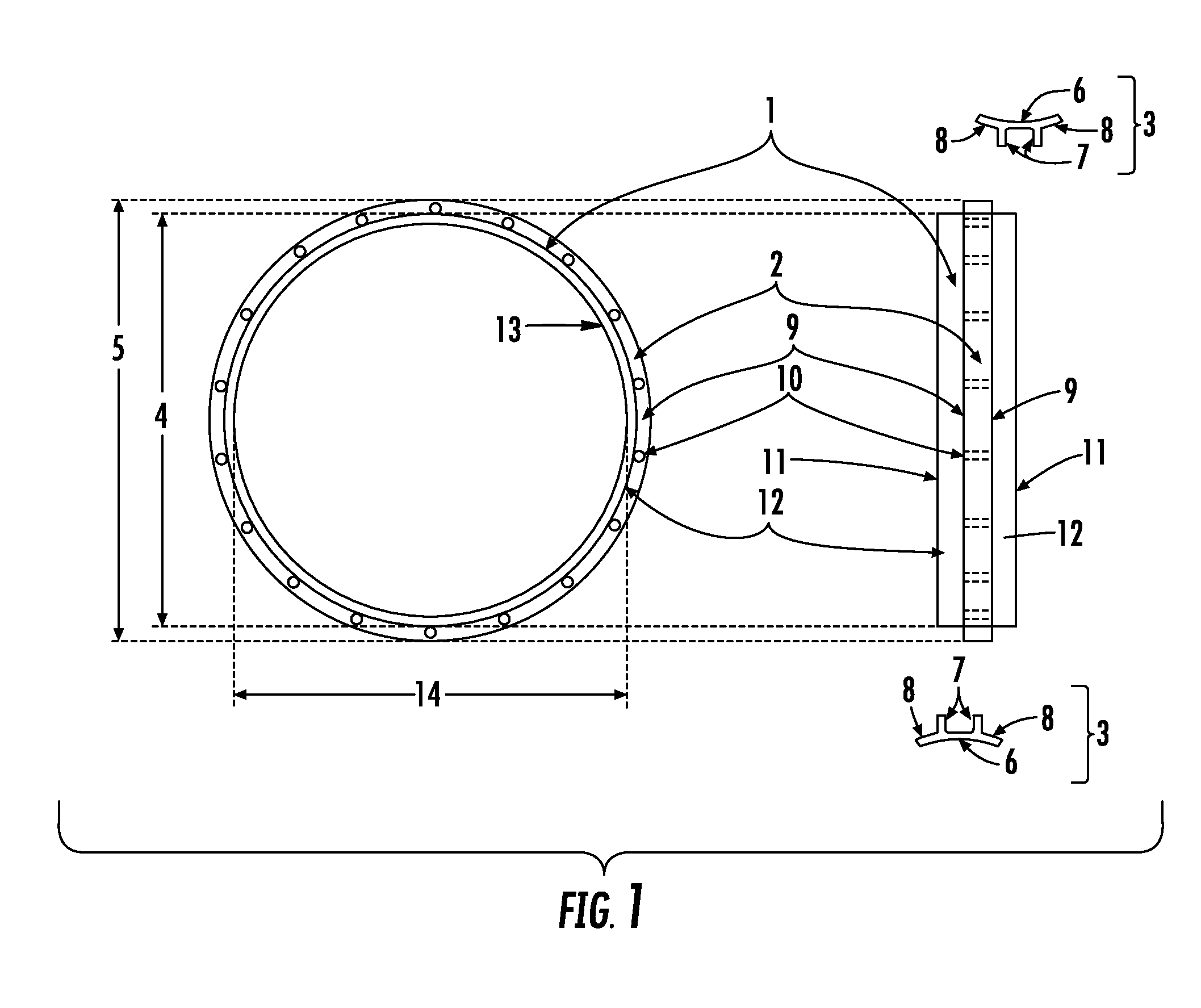
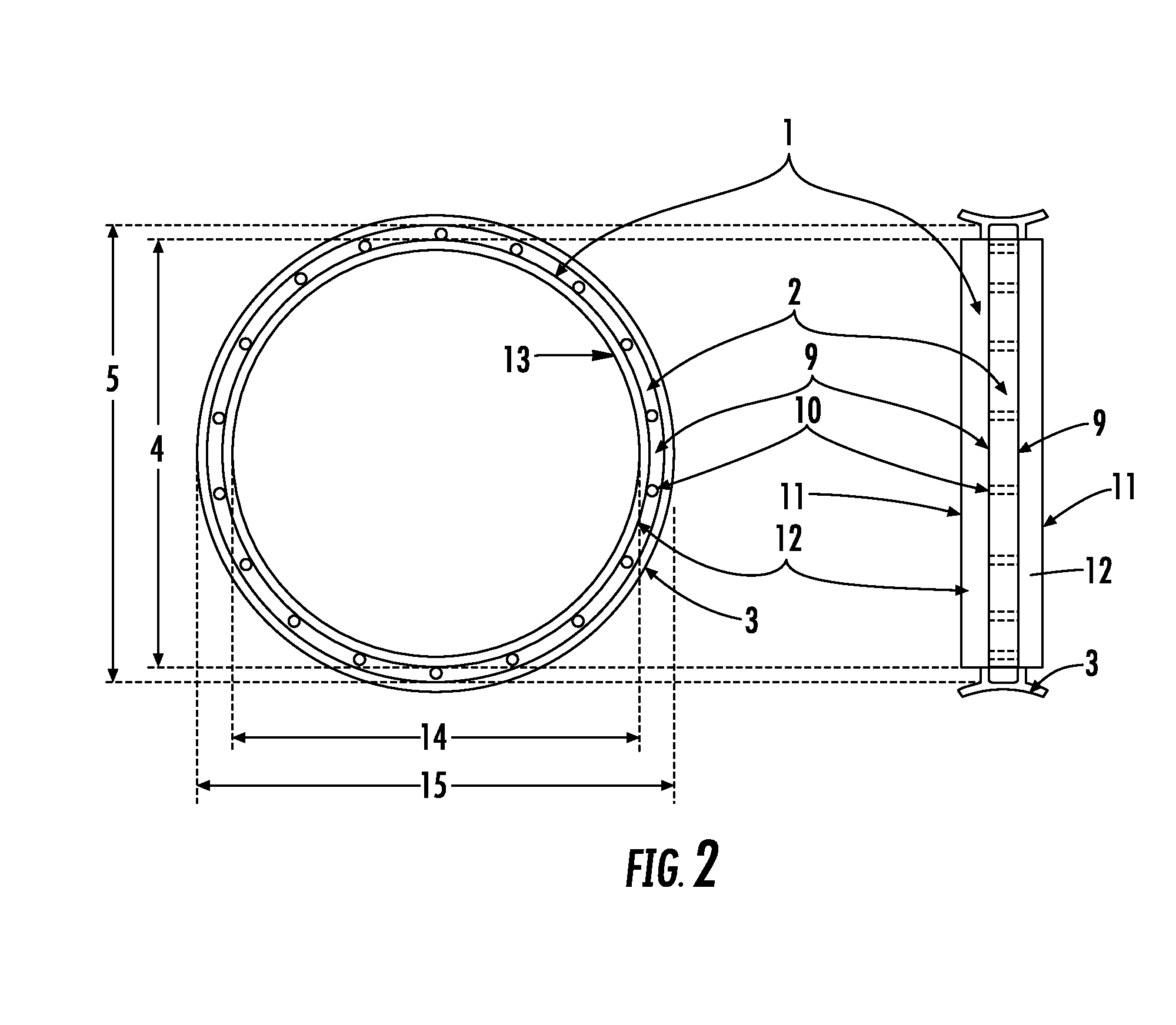
[0050]The valve body is generally in the shape of a ring or tube having an interior surface, an exterior surface and two ends. The occluder or the valve leaflets which are engaged in the interior surface of the valve body form no part of the present invention and are included for the better understanding of the invention. The preferred embodiment comprises forming a suture ring as portion of the valve body and having an implantation flap assembly.

[0051]The suture ring created on the exterior surface of the valve body along with the implantation flap assembly is adapted to engage and / or secure the valve body with the heart valve annulus. A plurality of pre-fabricated suture tunnels of an axial orientation is formed on the suture ring portion of the valve body through which the surgeon inserts the sutures. In one embodiment a knit fabric implantation flap assembly attached to the valve body surrounding the suture ring fits over an outer surface of the heart valve. The invention is dir...


PUM


Abstract

A mechanical heart valve implantable as heart valve replacement comprising of an annular valve body with a central orifice and an exterior surface incorporating a suture ring having a plurality of suture tunnels, and a valve implantation flap assembly disposed on the valve body surface and wrapping around the suture ring. The inside lumen carries the occluder mechanism. The valve holder comprises of at least two parts, both parts having suture guiding grooves on the outer surface corresponding to and matching with the tunnels on the suture ring, such as to form a continuous path for the sewing material. The parts of the valve holder can be detached separately from the valve after taking all the sutures, the part on the ventricular side before lowering the valve into the heart and the other part after lowering and positioning the heart valve in the; desired position inside the heart.

Description

FIELD OF INVENTION[0001]The present invention relates to the mechanical heart valve implantable and workable in lieu of defective natural heart valves.BACKGROUND OF THE INVENTIONHeart Valve Disease and Prosthetic Heart Valve Replacement[0002]The heart is a muscular pump which is continuously pumping blood from the time it develops in the fetus till the death of the individual. The heart is actually two independent pumps, bound together into one organ. The right heart pumps the deoxygenated blood and the left heart pumps the oxygenated blood. The heart has four chambers. The atria are thin walled and receive the blood into the heart, right atrium receives deoxygenated blood from the body and left atrium receives oxygenated blood from the lungs. The blood from the atria goes into the right and left ventricles which are the pumping chambers. The ventricles pump out the blood into the great arteries (pulmonary artery on the right side and aorta on the left side). There are valves locate...

Claims


Application Information

Patent Timeline
Patent Type & Authority Patents(United States)
IPC IPC(8): A61F2/24
CPCA61F2/2409A61F2/2427
Inventor KURIAN, VALIKAPATHALIL MATHEW
Owner KURIAN VALIKAPATHALIL MATHEW
Why Eureka
Try Eureka