Chromatograph mass spectrometer

a mass spectrometer and chromatograph technology, applied in the field of chromatograph mass spectrometer, can solve the problems of difficult to precisely perform this setting and inability to correctly perform quantitative analysis, and achieve the effect of reducing the labor required for input operation, preventing input errors, and reducing operator's workload

Active Publication Date: 2012-05-01
SHIMADZU CORP
View PDF16 Cites 7 Cited by
  • Summary
  • Abstract
  • Description
  • Claims
  • Application Information

AI Technical Summary

Benefits of technology

[0024]The chromatograph mass spectrometer according to the present invention greatly reduces the labor for the input operation necessary for setting measurement conditions for a simultaneous scan / SIM measurement, whereby the operator's workload is reduced and input errors are prevented. The graphical presentation of various types of information necessary for setting or correcting the measurement time range enables the operator to intuitively understand the situation and correctly set the measurement time range by simple operations. For example, even if a resultant chromatogram has two peaks located considerably close to each other, it is easy to avoid the situation where one of the boundaries of the measurement time ranges intervenes between the two peaks. Thus, the simultaneous scan / SIM measurement can be performed with higher degrees of accuracy.

Problems solved by technology

Another problem relates to the setting of a time range for the simultaneous scan / SIM measurement.
This situation leads to an incorrect detection of the peak and wrong calculation of the peak area, so that the quantitative analysis cannot be correctly performed.
However, in the case of conventional apparatuses, it is difficult to precisely perform this setting since the apparatuses have no means for referring to the preliminarily obtained chromatogram on the same screen when setting the time range for the simultaneous scan / SIM measurement as described earlier.

Method used


Image

  • Chromatograph mass spectrometer
  • Chromatograph mass spectrometer
  • Chromatograph mass spectrometer

Examples


Embodiment Construction

[0032]A gas chromatograph / mass spectrometer (GC / MS) is hereinafter described as an embodiment of the present invention.

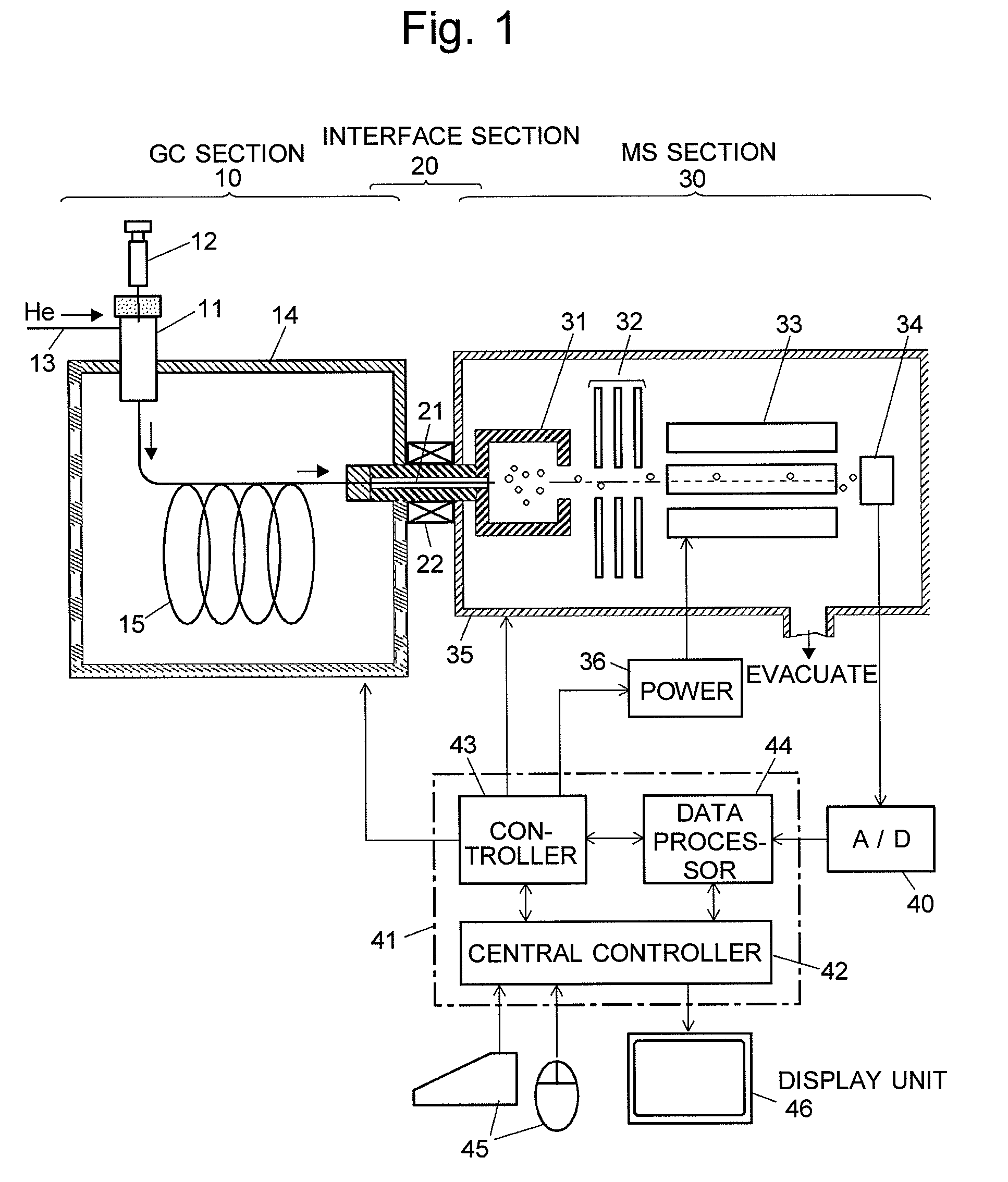
[0033]FIG. 1 is an overall configuration diagram of the GC / MS in the present embodiment. A gas chromatograph (GC) section 10 includes a sample-vaporizing chamber 11 at the inlet of a column 15 heated by a column oven 14 at appropriate temperatures. A carrier gas is supplied through a carrier-gas channel 13 into the sample vaporization chamber 11 at a predetermined flow rate and then flows into the column 15. In this situation, when a small quantity of liquid sample is injected from a microsyringe 12 into the sample-vaporizing chamber 11, the liquid sample becomes immediately vaporized, and the carrier gas conveys the vaporized sample (“sample gas”) into the column 15. While passing through the column 15, the components of the sample gas are temporally separated and individually reach the outlet of the column 15. Then, the components enter an interface section 20, wh...


PUM


Abstract

In a chromatograph mass spectrometer capable of defining an appropriate measurement time range and selectively performing a scan measurement, selected ion monitoring (SIM) measurement or simultaneous scan / SIM measurement in that time range, a total ion chromatogram 51 obtained by a scan measurement of a standard sample and a previously-created compound table 52 are displayed on the screen of a display unit in the process of setting parameters in a measurement condition table. An operator selects a compound that should undergo the simultaneous scan / SIM measurement, then places a checkmark in an appropriate check box in the compound table 52, and finally clicks the “Auto-Create” button 54. Then, a measurement time range for the selected compound is defined by adding a time span before and after the retention time of that compound, respectively, and a measurement condition table 53 is automatically created and displayed on the screen. This table includes instructions for performing a simultaneous scan / SIM measurement at specific mass-to-charge ratios characteristic of the selected compound during the aforementioned measurement time range.

Description

TECHNICAL FIELD[0001]The present invention relates to a chromatograph mass spectrometer, such as a gas chromatograph / mass spectrometer (GC / MS) or liquid chromatograph / mass spectrometer (LC / MS), in which a chromatograph is combined with a mass spectrometer. Specifically, it relates to a chromatograph mass spectrometer capable of simultaneously collecting data by a scan measurement and selected ion monitoring measurement.BACKGROUND ART[0002]The measurement methods of chromatograph mass spectrometers such as the GC / MS or LC / MS can be classified into two modes, i.e. the scan measurement and the selected ion monitoring (SIM) measurement. In the scan measurement mode, the mass spectrometer scans the mass-to-charge ratios (m / z) of ions to be analyzed over a predetermined mass range in order to detect all varieties of ions included in the aforementioned mass range. This mode of measurement is particularly useful in the case where the mass-to-charge ratio of the component of interest is unkn...

Claims


Application Information

Patent Timeline
Patent Type & Authority Patents(United States)
IPC IPC(8): B01D59/44
CPCG01N27/62G01N30/8651G01N30/8675G01N30/7233G01N30/8658G01N30/8696G01N27/623
Inventor SUMIYOSHI, TAKASHI
Owner SHIMADZU CORP
Why Eureka
Try Eureka