Prevention of core failures in large electric machines

a technology of dynamoelectric machines and cores, which is applied in the direction of dynamo-electric machines, dynamo-electric machine testing, magnetic circuit shapes/forms/construction, etc., can solve the problem of no mechanism to remove this eddy heat from the coolant gas, localized heating and melting of the core, and the phenomenon known as a core failure, so as to prevent loose laminations from rattling, reduce the risk of core failure, and prevent large eddy curren

Inactive Publication Date: 2012-05-15
RAO DANTAM K
View PDF33 Cites 18 Cited by
  • Summary
  • Abstract
  • Description
  • Claims
  • Application Information

AI Technical Summary

Benefits of technology

[0011]A major objective of the present invention is to describe a method of assembling the stator core that reduces the risk of core failure. Another objective is to prevent loose laminations from rattling. Another objective is to prevent large eddy currents from flowing through keybars. Another objective is to prevent eddy currents from causing core-end heating. Another objective is to isolate the frame from vibrations of the core. Another objective is to permi

Problems solved by technology

Under certain extreme operating and manufacturing conditions, the magnetic fields can cause localized heating and melting of the core in a phenomenon known as a core failure.
These in-depth studies pointed to excessive eddy currents created by shorts as the root cause of core failures.
Further, there is no mechanism to remove this eddy heat to the coolant gas.
So when large eddy currents flow through a small shorted spot, the local temperature shoots up and burns the insulative coating in adjacent laminations, causing additional axial shorts.
The insulation shorts thus amplify eddy currents and expand the melt zone uncontrollably, resulting in a core failure.
Even though laborious and expensive, recoating is the most widely used and proven method.
However, the recoat layer itself may embed conductive particles such as iron debris from deburring operation or slivers from punching operation, which reduces the dielectric breakdown voltage, increasing the core failure risk.
However, such shorting of keybars to all laminations unwittingly closes eddy loops and generates more eddy currents, increasing the core failure risk as already described.
Further, there is no easy path to transfer the eddy heat from the trapped straps into a cooling medium, so the straps become

Method used


Image

  • Prevention of core failures in large electric machines
  • Prevention of core failures in large electric machines
  • Prevention of core failures in large electric machines

Examples


Embodiment Construction

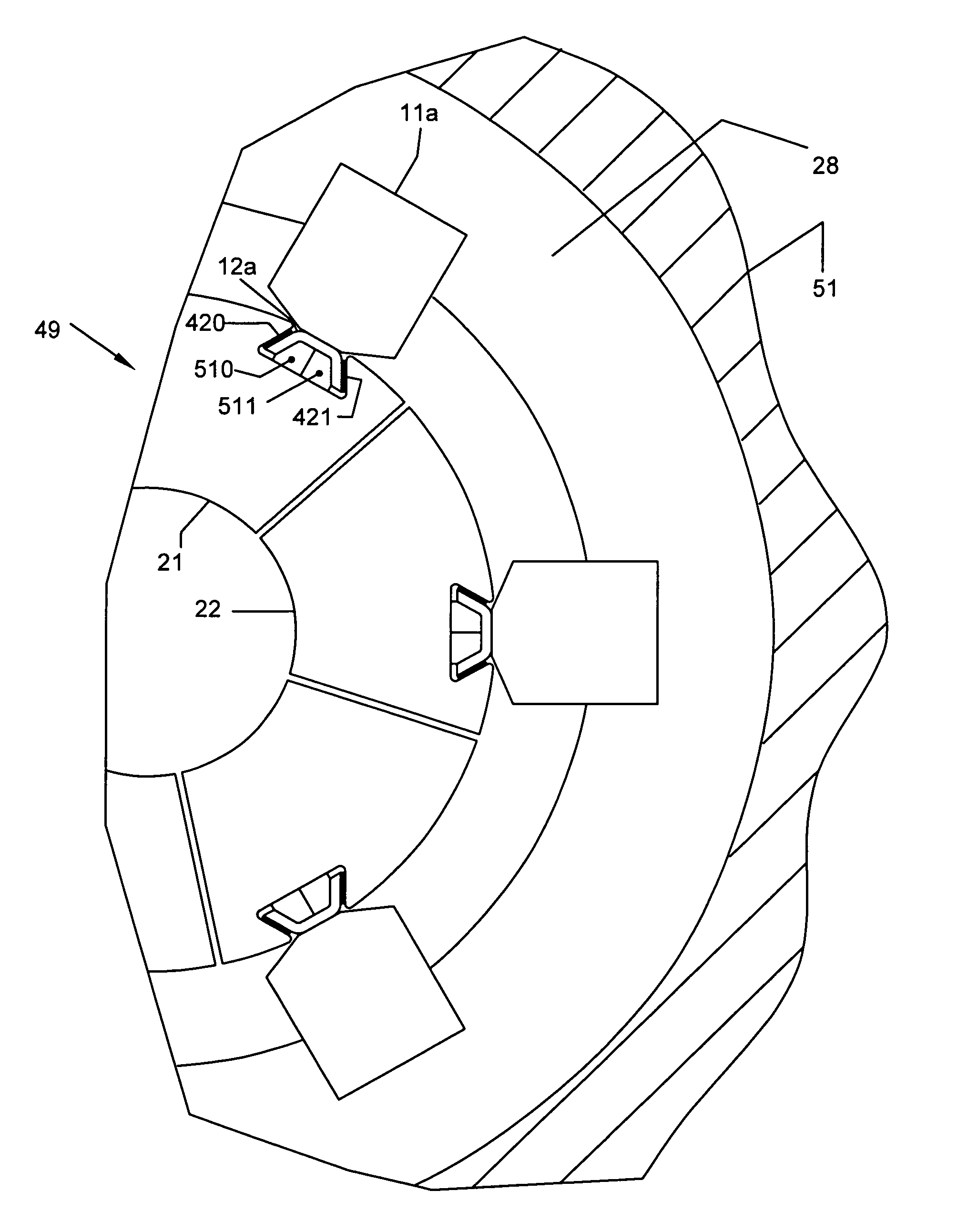
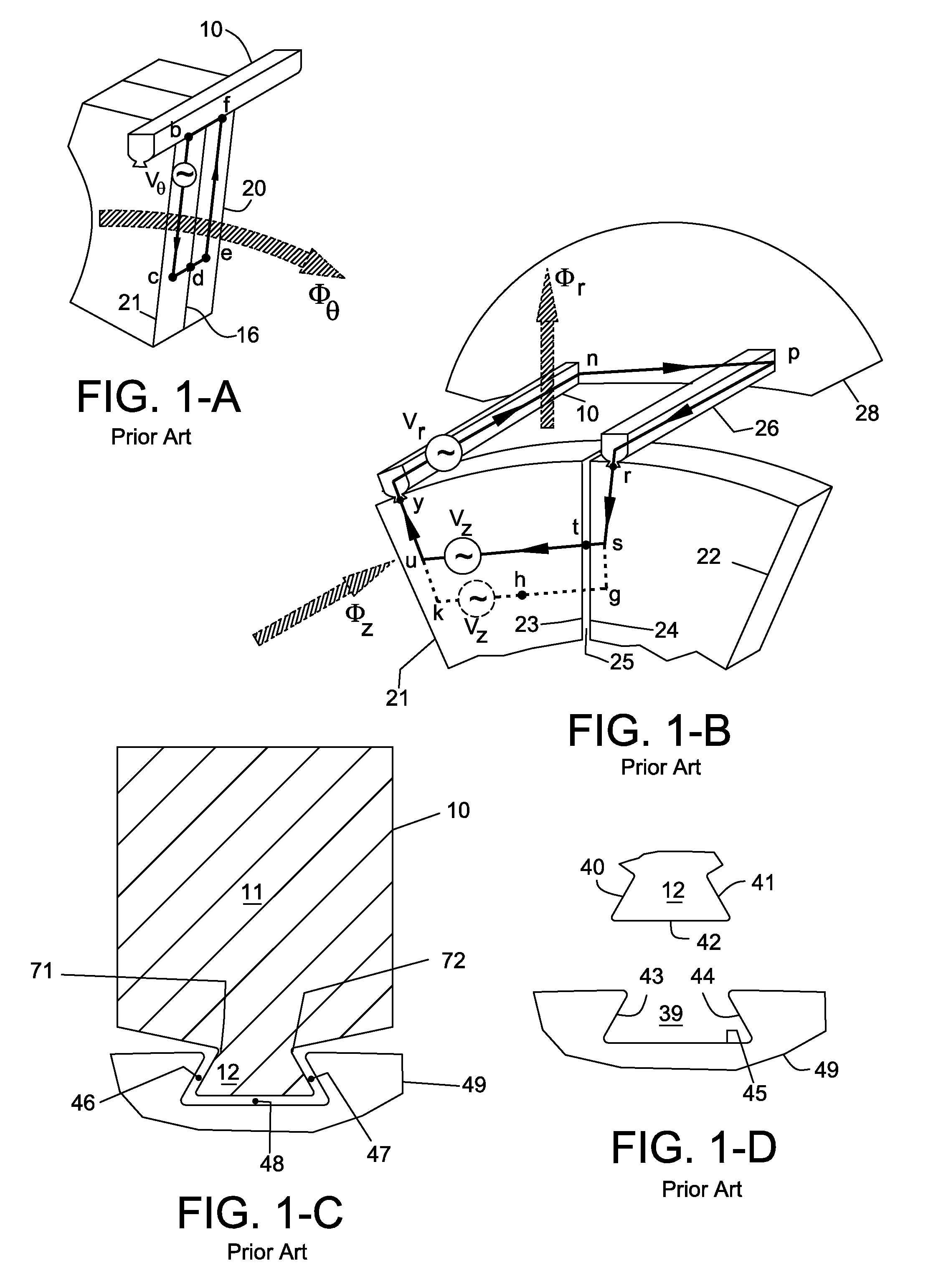
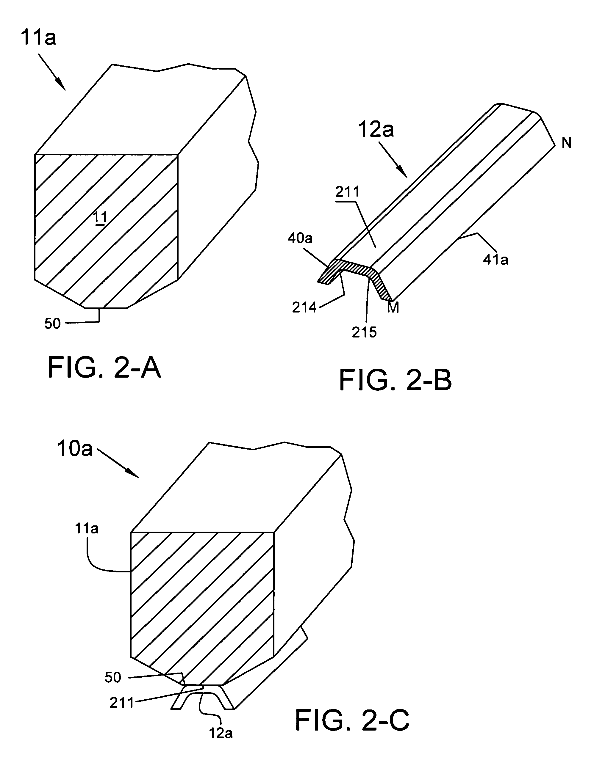
[0025]FIG. 2-A shows the bald keybar 11a to compress the core and transmit the loads from core to frame. It is a conventional keybar 10 without the dovetail 12 (see FIG. 1-C). Its size and shape is identical to the solid bolt portion 11 of the conventional keybar 10. It is made of same material and has threaded ends as in conventional keybar. A peripheral array of bald keybars 11a is secured to the frame 51 by welding to the support rings 28 and form a bald keybar cage as shown in FIG. 4. Bald keybar 11a has a narrow face 50 corresponding to the neck of the conventional keybar; this face is machined flat. Optionally machining of the face 50 can be done in-situ after the bald keybars are welded to the support ring, thereby avoiding any weld distortions affecting the flatness of faces 50 and roundness of array of bald keybars. Faces 50 of array of bald keybars could define a reference round surface for building the core. Since the bald keybar 11a has no dovetail, it is simpler and les...


PUM


Abstract

The keybar that is attached to the frame of a dynamoelectric machine is broken into a bald keybar with mini-dovetails attached to it. The bald keybar is identical to the bolt portion of a conventional keybar. The mini-dovetail is a trapezoidal or U-shaped strip with insulated slanted arms. The core packet is inserted loosely over an array of mini-dovetails. Devices such as wedges, threaded rods flex the slanted arm and press them against the slot faces of the core packet, thereby locking the core packet to the frame. Insulation on the slanted arms prevents large eddy currents due to shorted laminations, increasing the machine efficiency. Preventing large eddy currents also eliminates hot spots which could otherwise cause a core failure. Locking the core packets also prevents rattling of laminations. The locking method also distributes the torque forces evenly around the periphery.

Description

FIELD OF THE INVENTION[0001]The present invention relates to preventing core failures in large dynamoelectric machines, particularly those caused by large eddy currents circulating within its laminations and keybars. It also relates to the method of mounting the laminations over keybars.BACKGROUND[0002]The frame of a dynamoelectric machine contains at its inner periphery an array of keybars, i.e., long metallic rods formed with a bolt portion that compresses the core and mounts the laminations in its dovetail slot. The core is a long hollow cylinder, made of hundreds of thousands of laminations that are punched from an insulated silicon steel strip to a segment shape. At the periphery, each lamination has dovetail slots, one of which engages the dovetail portion in the keybar. The laminations are mounted over the keybars in a circular fashion to form a first annular planar array, each separated by a small air gap called a segment gap. A second annular array is stacked on top of the ...

Claims


Application Information

Patent Timeline
IPC IPC(8): H02K1/18
CPCH02K1/185G01R31/34
Inventor RAO, DANTAM K.
Owner RAO DANTAM K
Why Eureka
Try Eureka