Liquid food dispenser system and method

a liquid food dispenser and liquid technology, applied in liquid handling, pliable tubular containers, instruments, etc., can solve the problems of difficult cleaning and sanitization of the system, increased risk of bacterial contamination, and inconvenient use of the system, so as to achieve the effect of simply and accurately determining the volume of the remaining produ

Active Publication Date: 2012-05-22
FAIRLIFE LLC
View PDF39 Cites 49 Cited by
  • Summary
  • Abstract
  • Description
  • Claims
  • Application Information

AI Technical Summary

Benefits of technology

[0022]In accordance with another preferred embodiment of the present invention, a system for dispensing a liquid beverage system comprises a gas-tight chamber having an interior environment, a compressible container containing the liquid beverage, the compressible container disposed inside of the gas-tight chamber, wherein the compressible container isolates the liquid beverage from the gas-tight chamber interior environment, a nozzle for dispensing the liquid beverage in the compressible container, wherein the nozzle seals the liquid beverage from an external environment when the nozzle is closed and minimizes a surface area of surfaces exposed to both the liquid beverage and the external environment, a gas source providing gaseous pressure in the gas-tight chamber, the gaseous pressure exerting force on an external surface of the compressible container, a pressure sensor disposed within the gas-tight chamber interior environment, a temperature sensor disposed within the gas-tight chamber interior environment, and an electronic controller controlling the gas source based on input from the pressure sensor and the temperature sensor.
[0028]In accordance with another preferred embodiment of the present invention, a system for dispensing a liquid beverage comprises a source of a liquid beverage, the source being under pressure, a nozzle coupled to the source, wherein the pressure causes the liquid beverage to flow from the source to the nozzle when the nozzle is in an open position, and a hat valve attached to the nozzle, wherein the hat valve prevents flow of the liquid beverage from the nozzle to the source.
[0037]In accordance with another preferred embodiment of the present invention, a system for dispensing a liquid beverage comprises a first liquid storage container disposed within a first chamber, the first liquid storage container comprising an outlet for dispensing the liquid beverage, a second liquid storage container disposed within a second chamber, the second storage container comprising an outlet for dispensing the liquid beverage, a first check valve coupled to the first liquid storage container outlet, wherein the first check valve is oriented so that the liquid beverage is prevented from flowing back toward the first liquid storage container, a second check valve coupled to the second liquid storage container outlet, wherein the second check valve is oriented so that the liquid beverage is prevented from flowing back toward the second liquid storage container, and a tee fitting comprising a first input port coupled to the first check valve, a second input port coupled to the second check valve, and an exit port.
[0047]An advantage of a preferred embodiment of the present invention is that generally there is no external contact with the liquid food product except for at the nozzle tip. Such a lack of external contact provides a sanitary environment and decreases the risk of bacterial contamination of the liquid food product. The liquid food product is further protected from bacterial contamination because the propellant gas acts against the walls of the bag containing the liquid food product and does not come in contact with the liquid food product to be dispensed.
[0049]Yet another advantage of a preferred embodiment of the present invention is that the volume of the remaining product can be simply and accurately determined without any additional scales or sensors, and without requiring any additional cleaning steps as would be required by systems in which the dispensed product comes in physical contact with the measuring device.

Problems solved by technology

A disadvantage of this type of prior art pump is that the ingredient being pumped comes in direct contact with internal parts of the diaphragm pump.
Such contact increases the risk of bacterial contamination and makes the system difficult to clean and sanitize.
One disadvantage with using a peristaltic pump is that whenever new product is loaded into the system, the operator must mate the disposable tube to the permanent peristaltic pump tube.
Another disadvantage of the peristaltic pump is that the permanent tube comes in contact with the product and must be washed out regularly to maintain appropriate levels of sanitation.
A major drawback with this method, however, when applied to edible or organic products, is that the propellant gas coming in direct contact with the product makes the product more prone to spoilage or environmental contamination.
One disadvantage of the gravity flow system, however, is that the flow rate of the dispensed liquid is dependent on the head pressure of the ingredients.
A second disadvantage of the gravity flow system is that more viscous ingredients will flow at unacceptably slow flow rates.
This is particularly an issue with low-acid products that are high in nutrients, which are particularly prone to bacterial growth.
One disadvantage with this method is that once the tube is cut, it cannot be resealed without resorting to a mechanical means to pinch the tube shut.
Another disadvantage with this method is that the end of the tube is exposed to the environment, resulting in the possibility of contamination and the potential for the ingredient to dry in the tube.
Another disadvantage is that, because the tube must be physically cut, the cutting device also requires cleaning and sanitizing.
In addition, the cutting device can be lost, dulled, misused and left unclean.
The tube can also be incorrectly cut, whether cut at an angle, jagged, or cut too high or too low on the tube.
A disadvantage with this method is that it requires at least two external pieces.
Another disadvantage with this method is that these external pieces and the associated pumping mechanism need to be cleaned regularly or replaced if good sanitation is to be maintained.
Another issue with prior art beverage dispensing machines involves automatic product changeover for beverage dispensing systems that employ a plurality of product storage containers.
A disadvantage of sensing vacuum levels, however, is that an in-line device is necessary to determine if a vacuum level is low.
An in-line device, such as a vacuum sensor, can come in contact with the beverage and create contamination issues.
Another issue with prior art beverage dispensing machines involves splattering during the initiation of dispensing.
With some nozzle designs, there may be a problem during the opening or closing of the nozzle, especially when the opening or closing is performed slowly.
As the nozzle plunger lifts into the nozzle body, breaking the nozzle seal and allowing product to flow through the newly-created gap, the flow may disassociate and splatter as it dispenses in a non-uniform fashion.
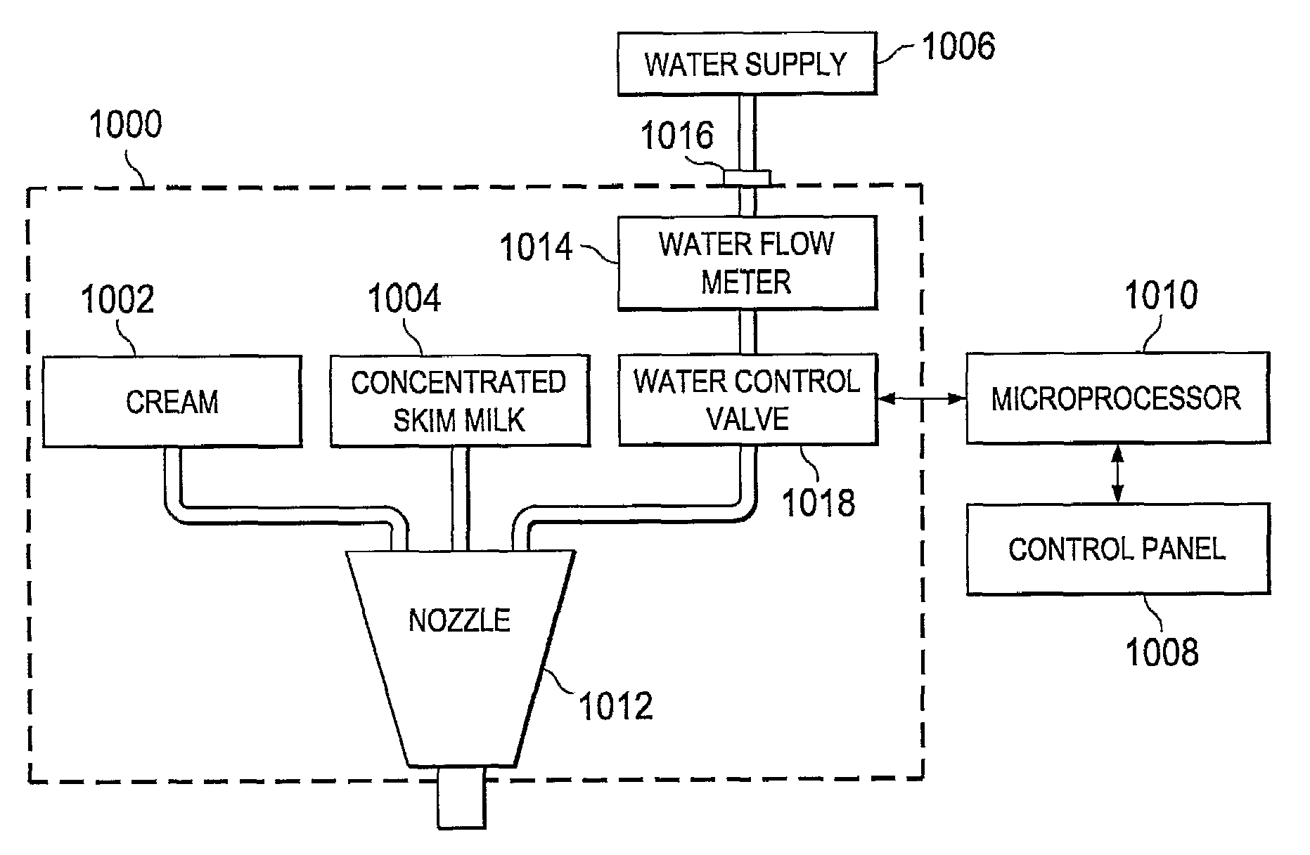
Another issue with prior art beverage dispensing machines it that prior art machines have been unable to provide precise mixtures of various dairy products, for example, milk, cream, and water.
While mixing dairy products is used in the large scale commercial production of dairy goods, an ability to mix dairy products on the fly in a dispensing machine has not been introduced in dairy dispensing machines.
One of the difficulties in providing dairy mixtures is that precisely controlling the ratios of dairy products is difficult to achieve with gravity flow dairy dispensing devices, and also machines that dispense individual servings.
Another difficulty involves mixing different products in a manner that is not apparent to the user.
Yet another issue with beverage dispensing systems pertains to tracking the amount of remaining product left in the machine that is available for dispensing.
Indirect methods of determining remaining product quantity, however are prone to error because of inaccuracies in flow rate assumptions and inaccuracies in initial product volume.
A disadvantage of this method is that the sensing system or portions of the sensing system sit below the ingredient container.
Since food ingredient containers need to be washable, any sensor that sits below an ingredient container may be prone to issues relating to cleaning, sanitation, and difficulties caused by spilling or leaking ingredients.
Another problem with the load cell approach is that the product package is usually attached to the product cavity whose volume is being measured.
Since the product package is weighed along with the product inside it, measuring inaccuracies may result.
A disadvantage of the in-line sensing method is that it requires measuring devices that come in physical contact with the product.
This is a potential source of contamination that requires proper cleaning and sanitation.

Method used


Image

  • Liquid food dispenser system and method
  • Liquid food dispenser system and method
  • Liquid food dispenser system and method

Examples


Embodiment Construction

[0089]The making and using of the presently preferred embodiments are discussed in detail below. It should be appreciated, however, that the present invention provides many applicable inventive concepts that can be embodied in a wide variety of specific contexts. The specific embodiments discussed are merely illustrative of specific ways to make and use the invention, and do not limit the scope of the invention.

[0090]The present invention will be described with respect to preferred embodiments in a specific context, namely a beverage dispensing machine. The invention may also be applied, however, to other dispensing systems, or other systems with sanitary or fluid measurement requirements.

[0091]In illustration of one embodiment of the present invention, FIG. 1a shows a three-dimensional view of a beverage dispensing machine 10. The liquid product is stored in a bag (not shown) disposed within boxes 16a and 16b. The liquid product could be milk, juice, beverage concentrate, or other ...


PUM


Abstract

A system and method for dispensing fluids is introduced. A preferred embodiment comprises a sealed tank, a bag containing fluid inside the sealed tank, an outlet for dispensing the liquid in the bag, and a pressure generating device to create pressure in the sealed tank.

Description

RELATED APPLICATION DATA[0001]This application is a national filing under 35 U.S.C. 371 of International Application No. PCT / US2007 / 0015663, filed on Jul. 6, 2007, which application receives the benefit of and claims priority to two U.S. Provisional Applications: U.S. Provisional Application No. 60 / 819,178, filed on Jul. 7, 2006, entitled “Liquid Food Dispenser System and Method,” and U.S. Provisional Application No. 60 / 912,626, filed on Apr. 18, 2007, entitled “Liquid Food Dispenser System and Method,” all of which applications are hereby incorporated herein by reference.TECHNICAL FIELD[0002]The present invention relates generally to a system and method of dispensing fluids, and more particularly to a system and method for dispensing liquid beverages.BACKGROUND[0003]Beverage dispensing machines generally are intended to expel or deliver a beverage or beverage concentrate in a reasonably sanitary manner. Generally, beverage dispensing machines require a mechanism to pump or expel th...

Claims


Application Information

Patent Timeline
Patent Type & Authority Patents(United States)
IPC IPC(8): A23C9/00B67D1/04B67D7/72B67D7/80
CPCB67D1/0082B67D1/0462B67D1/0864B67D1/1245B67D1/1277B67D1/1252B67D2210/0006B67D2210/00062B67D2001/0828B67D1/0021B65D47/242B65D47/244
Inventor DOELMAN, TIMOTHY PETERBAXTER, VINCENT A.
Owner FAIRLIFE LLC
Why Eureka
Try Eureka