High-speed charging power supply device and high-speed charging power supply method

a power supply device and high-speed technology, applied in the direction of emergency supply, electric devices, and arrangements for several simultaneous batteries, can solve the problem of taking a relatively long time to charge, and achieve the effects of enhancing the mobility of the mobile body, and saving considering noise and surg

Inactive Publication Date: 2012-05-22
INST FOR ENERGY APPL TECH
View PDF20 Cites 32 Cited by
  • Summary
  • Abstract
  • Description
  • Claims
  • Application Information

AI Technical Summary

Benefits of technology

[0021]In the boosting-charge power supply apparatus according to claim 1 and the boosting-charge power supply method according to claim 2, when the mobile body is charged, the power-supply controlling means separates the power supplying means and the first power storing means electrically to thereby allow only the first power storing means to supply electric power to the mobile body. The mobile body having the boosting-charge control function executes control in such a way that pure DC power supplied from the first power storing means becomes electric power suitable for the charging conditions of the second power storing means, thereby enabling the same boosting-charge power supply apparatus to supply electric power and give a boosting charge to a different type of mobile body. The boosting-charge control function is extremely significant because it may affect the life or the like of the second power storing means. In designing a mobile body having a boosting-charge control function, the boosting-charge control function can be determined by fully studying characteristics of the second power storing means. Conventionally, a boosting-charge apparatus and a mobile body such as a vehicle are each produced by a separate manufacturer, but a mobile body is provided with a boosting-charge control function, thereby enabling the mobile-body manufacturer to design the second power storing means and the boosting-charge control function together. This makes it possible to design the second power storing means in such a way that it has a higher performance, thereby enhancing the mobility of the mobile body. Besides, the mobile body can be supplied with high-quality electric power equivalent to pure DC power, thereby almost saving considering a noise, a surge or the like in designing electric circuits of the mobile body, so that the electric circuits of the mobile body can be more easily designed.
[0022]In the boosting-charge power supply apparatus or boosting-charge power supply method according to claim 3, the first power storing means has the plurality of charging circuits connected in parallel thereto to thereby give a boosting charge simultaneously to the plurality of mobile bodies having different charging conditions.

Problems solved by technology

An electric vehicle, emitting no exhaust gas and environment-friendly, has the problem of taking a relatively long time to charge.

Method used


Image

  • High-speed charging power supply device and high-speed charging power supply method
  • High-speed charging power supply device and high-speed charging power supply method
  • High-speed charging power supply device and high-speed charging power supply method

Examples


first embodiment

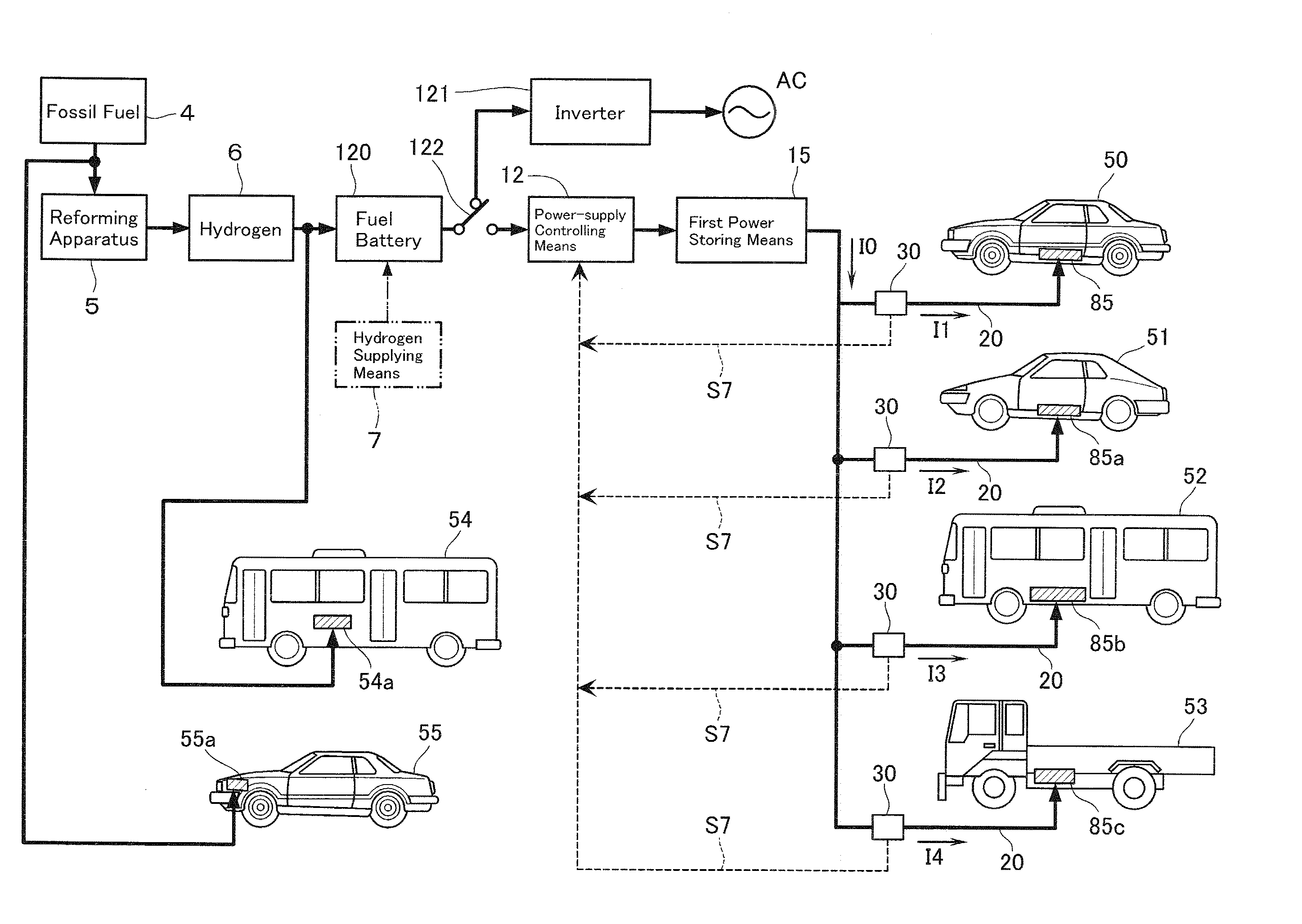
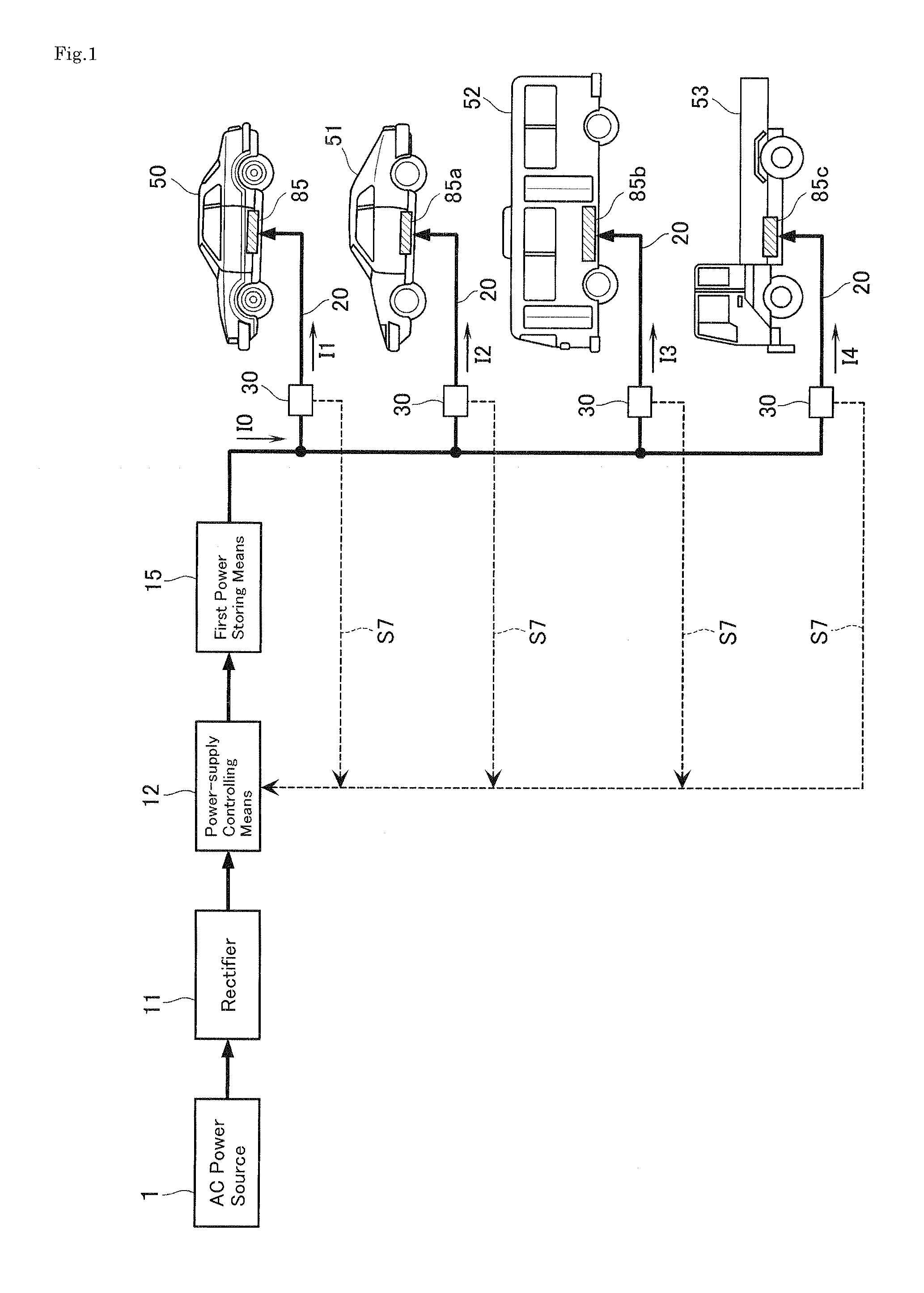
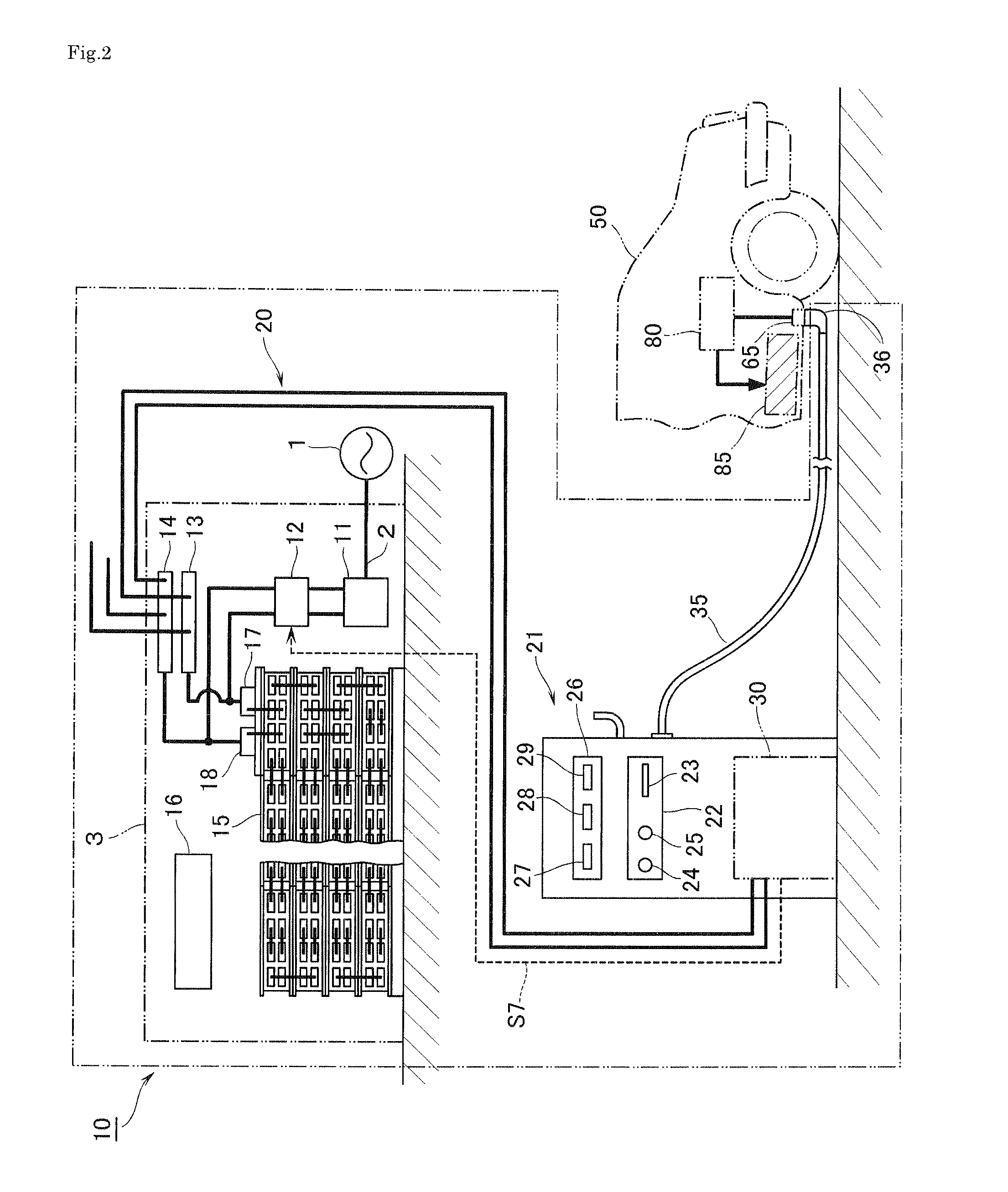
[0084]FIGS. 1 to 9 show a boosting-charge power supply apparatus according to a first embodiment of the present invention. In FIG. 2, reference numeral 1 denotes a commercial AC power source such as a three-phase AC power source which supplies electric power through a power line 2 into a construction 3. The construction 3 houses: a rectifier 11 as a power supplying means constituting a boosting-charge power supply apparatus 10; a power-supply controlling means 12; a first power storing means 15; and other equipment. The rectifier 11 is connected on the input side to the power line 2 inside of the construction 3 and has the function of converting three-phase AC power from the power line 2 into DC power after regulating it to a predetermined voltage. On the output side, the rectifier 11 is connected via the power-supply controlling means 12 to the first power storing means 15. As described later, the power-supply controlling means 12 has the function of stopping the rectifier 11 from ...

second embodiment

[0107]FIGS. 10 and 11 show a boosting-charge power supply apparatus 10 according to a second embodiment of the present invention which has the function of detecting a residual capacity (residual power amount) of the first power storing means 15. The second embodiment is different from the first embodiment in the above respect and charge hours for the first power storing means 15. Otherwise it is the same as the second embodiment, and hence, component elements are given the same reference characters and numerals as those of the first embodiment, as long as the former are identical to the latter, and their description is omitted embodiment. The same rule will also be applied to the other embodiments described later.

[0108]In FIG. 10, the first power storing means 15 is provided on the output side with a first power-amount sensor 91 measuring a power amount outputted from the first power storing means 15 and on the input side with a second power-amount sensor 92 measuring a power amount...

third embodiment

[0111]FIG. 12 shows a boosting-charge power supply apparatus according to a third embodiment of the present invention which is applied to a boosting charge for a ship as a mobile body. As shown in FIG. 12, a second power storing means 85d of a passenger ship 100, a second power storing means 85e of a motorboat 101, a second power storing means 85f of a car ferry 102 and a second power storing means 85g of a bathyscaphe 103 can be supplied with electric power for charge through each charging circuit 20 connected in parallel to the first power storing means 15. In view of improvements in the global environment, more ships propelled by electric power should desirably be used. As a prime mover for shipping, for example, a high-temperature superconducting motor having a high performance may desirably be employed. In this implementation, the pure DC power supplied from the first power storing means 15 is controlled to charge each ship, and thereby, the charging voltage and charging curren...


PUM

PropertyMeasurementUnit
open-circuit voltageaaaaaaaaaa
electric poweraaaaaaaaaa
DC poweraaaaaaaaaa

Abstract

A boosting-charge power supply apparatus which supplies electric power for charging a mobile body having a boosting-charge control function includes: a rectifier for supplying DC power; a first power storage for storing DC power from the rectifier and outputting DC power; a charging circuit which sends DC power from the first power storage directly to a vehicle including a second power storage for storing DC power from the first power storage; and a power-supply controller for stopping the rectifier from supplying electric power to the first power storage while the first power storage is supplying electric power to charge the second power storage. Through the controller, DC power supplied from the first power storage becomes suitable for charging of the second power storage on the vehicle side, thereby enabling the same boosting-charge power supply apparatus to supply electric power and give a boosting charge to a different type of vehicle.

Description

[0001]This application is a National Stage entry of International Application No. PCT / JP2008 / 000261, filed Feb. 19, 2008, the disclosure of the prior application is hereby incorporated in its entirety by reference.TECHNICAL FIELD[0002]The present invention relates to a boosting-charge power supply apparatus and a boosting-charge power supply method capable of supplying electric power for boosting charge to a mobile body such as a vehicle and a ship.BACKGROUND ART[0003]An electric vehicle, emitting no exhaust gas and environment-friendly, has the problem of taking a relatively long time to charge. In order to shorten the charge time, the electric vehicle has to be given a great amount of electric power in a short time, thereby requiring power equipment having a larger power capacity in a location where only a low-voltage power line is laid. Hence, an electric vehicle is generally given a boosting charge by rectifying commercial AC power, storing DC power in a storage battery and util...

Claims


Application Information

Patent Timeline
Patent Type & Authority Patents(United States)
IPC IPC(8): H02J7/00B60L1/00H01M8/00H01M8/06H01M8/10H01M10/44H01M10/60H01M10/613H01M10/625H01M10/633H01M10/637H01M10/6551H01M10/6563H01M10/6572H02J7/34
CPCB60L3/003B60L3/04B60L11/1816B60L11/1824B60L11/1825B60L11/184B60L11/1844B60L11/1846H01M10/441H01M10/5004H01M10/5016H01M10/5085H01M16/006H02J7/0027H02J7/0054B60L3/0046B60L2200/26B60L2200/10B60L2200/18B60L2200/28B60L2200/32B60L2200/36B60L2210/20B60L2210/30B60L2210/40B60L2230/16B60L2230/28B60L2230/30B60L2230/32H01M2250/00H01M2250/10Y02B90/14Y02T10/7005Y02T10/7055Y02T10/7088Y02T10/725Y02T90/121Y02T90/127Y02T90/14Y02T10/7241Y02T90/163Y02T90/169Y02T90/128Y04S10/126Y04S30/14Y02E60/721H01M10/625H01M10/6572H01M10/613B60L53/14B60L53/31B60L53/64B60L53/63B60L53/65B60L53/305B60L53/54B60L53/53B60L53/55H02J7/342B60L53/34Y02B90/10Y02E60/00Y02T10/70Y02T10/72Y02T10/7072Y02T90/12Y02T90/167Y02T90/16Y02E60/50Y02E60/10H02J7/0013H02J3/322H02J2310/44H02J2310/42H02J2310/48Y04S30/12
Inventor SUGANO, TOMIO
Owner INST FOR ENERGY APPL TECH
Why Eureka
Try Eureka