
Transforming variable domains for linear circuit analysis

a technology of linear circuit analysis and transform variables, applied in error detection/correction, program control, instruments, etc., can solve the problems of high cost associated with semiconductor photolithography and fabrication techniques, difficult to predict the actual performance of integrated circuit designs, and complex design and layout of integrated circuits

Inactive Publication Date: 2012-05-22
RAMBUS INC
View PDF7 Cites 8 Cited by
  • Summary
  • Abstract
  • Description
  • Claims
  • Application Information

AI Technical Summary

Problems solved by technology

Today, integrated circuits are extremely complex in design and layout.
Even the most knowledgeable circuit designers, working with state-of-the-art software design tools, find it difficult to predict how their circuit designs will actually perform.
The high costs associated with semiconductor photolithography and fabrication techniques make it imperative that the circuit design is working as close to optimal parameters as feasible, before the circuit design is committed to manufacturing.
However, transient analysis is inefficient in characterizing the circuit response to a wide class of input excitations (e.g. response to a step, ramp, sinusoid at various frequencies, or combinations thereof), mainly because it computes a response to one particular set of excitations.
Furthermore, the time-domain, nonlinear simulation algorithms used by transient analysis tend to be slower than other analyses in SPICE (e.g. DC or AC analyses).
Unfortunately, such an assumption limits the application of AC analysis only to circuits that have meaningful linear responses with voltages or currents as their input and output variables.
Another limitation of AC analysis is that it can only compute the linear response at a fixed (DC) operating point.
While PAC analysis overcame the limitation of AC analysis being applicable to only fixed DC operating points, the limitation of using only voltage or current variables in computing the linear response still remains.
All circuits exhibit linear responses to small-signal excitations, but not all of the linear responses are useful or meaningful to the designers.
For example, a phase-locked loop does not convey useful information directly when its linearized response to a small-signal sinusoidal change in the input clock voltage is simulated via PAC analysis.
However, this process of estimating the linear response via transient analysis is an extremely slow and computationally intensive procedure as compared to that of AC or PAC analysis.
Although transient analysis is slow, cumbersome, and consumes a great amount of processing power, circuit designers are faced with no other viable solution.

Method used


Image

  • Transforming variable domains for linear circuit analysis
  • Transforming variable domains for linear circuit analysis
  • Transforming variable domains for linear circuit analysis

Examples


Embodiment Construction

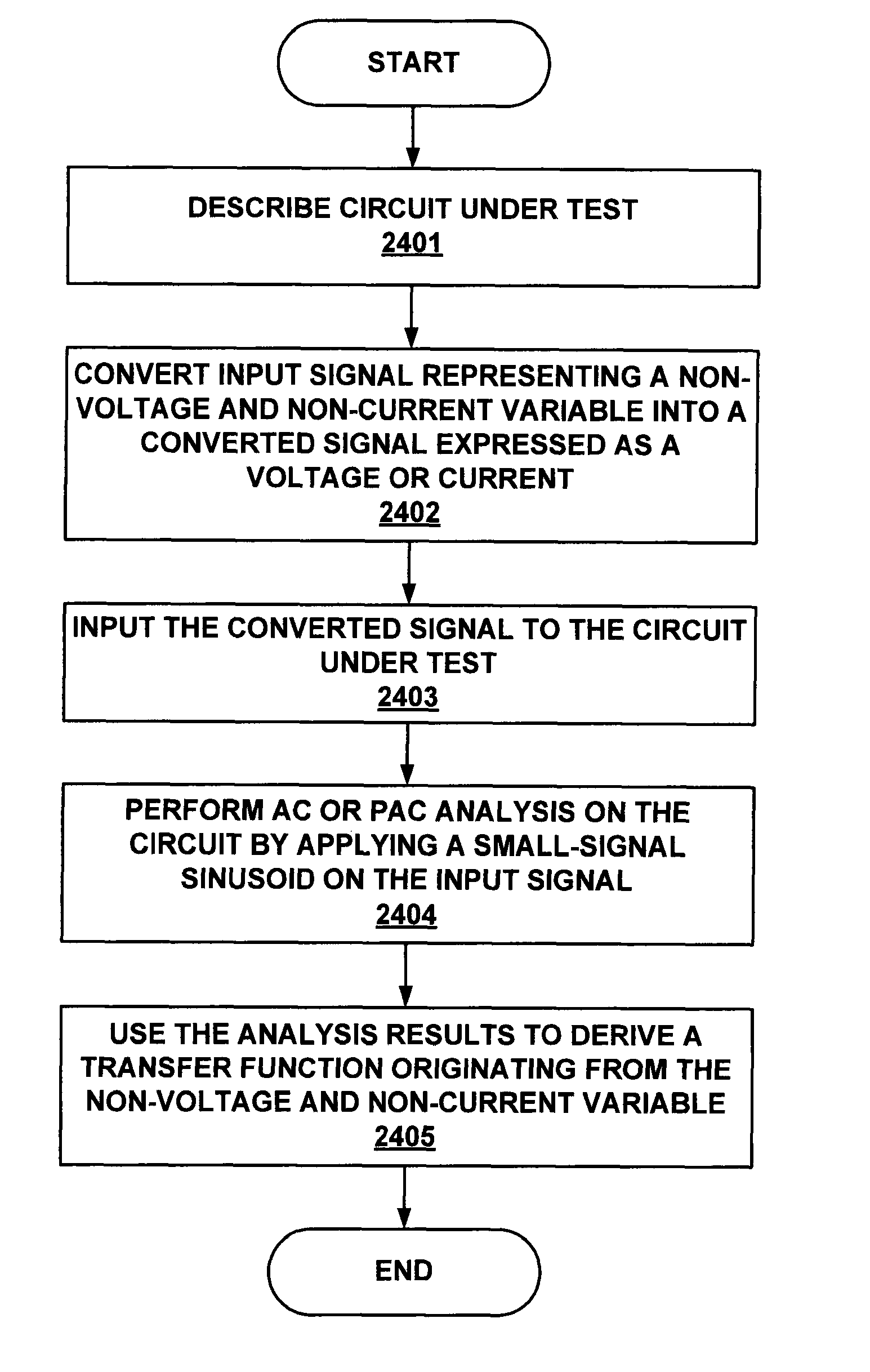
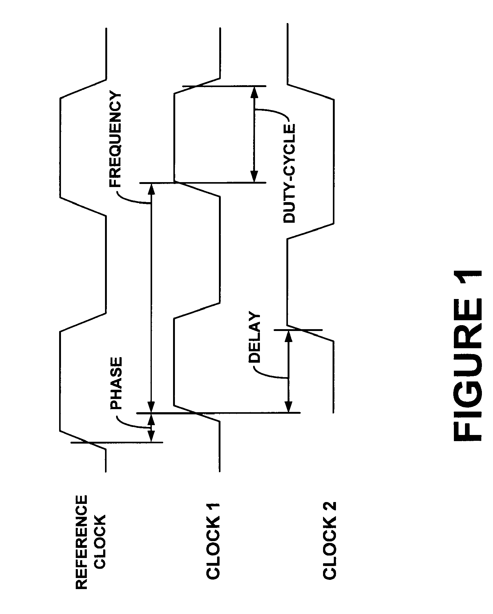
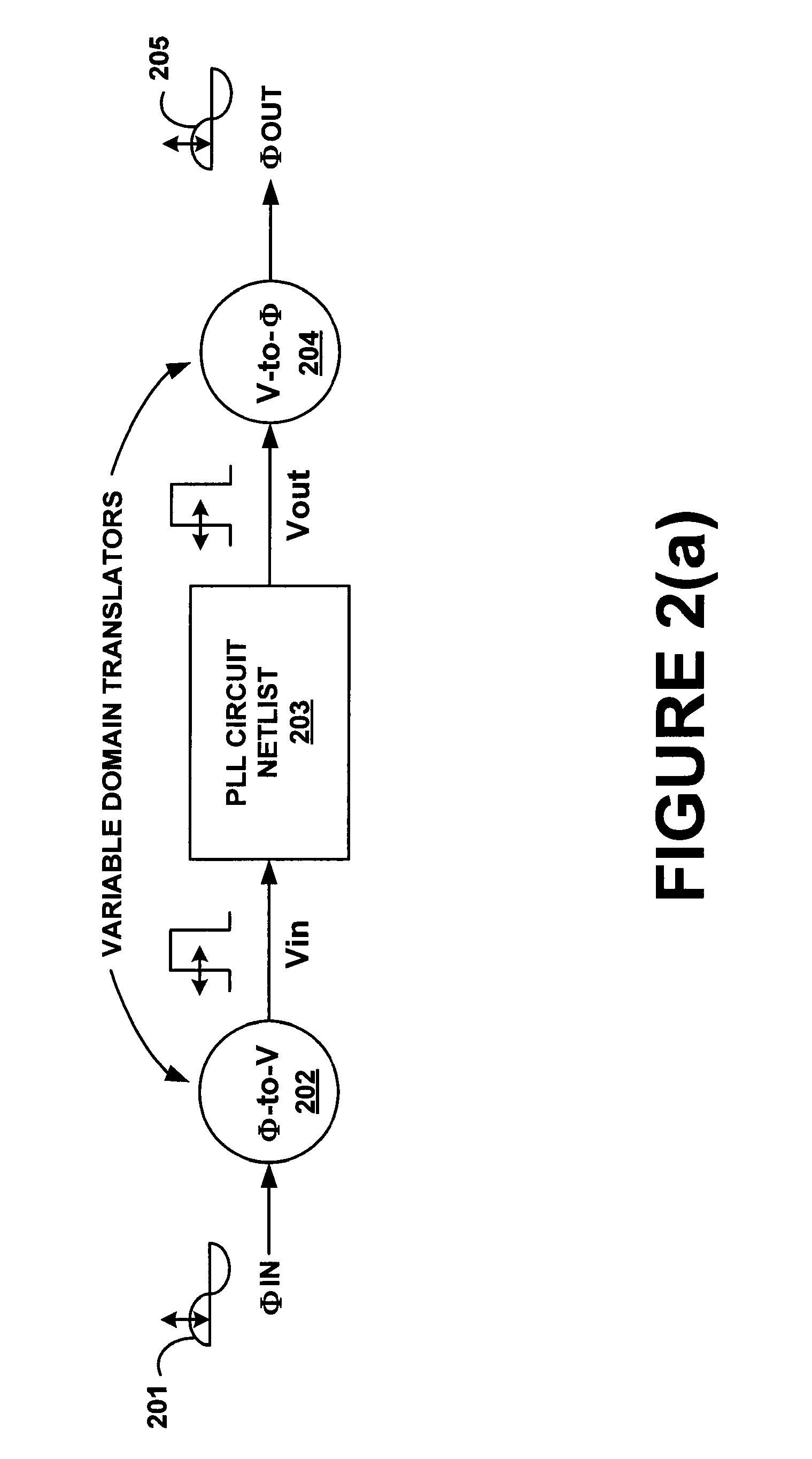
[0047]Embodiments in the present disclosure pertain to performing AC analysis in variables other than node voltage or branch current of the circuit. More than one variable domains may exist to describe the characteristics of an electrical signal. For example, one method to describe a periodic clock signal is its voltage waveform over time. In this case, the chosen variable domain is voltage. Another method would be the waveform of the clock's phase. In this case, the chosen variable is phase. Notice that the phase domain representation of the clock signal does not explicitly express the periodic waveform of the clock signal. It is rather implicitly assumed by the designer that the clock signal has a known periodic waveform such as a sinusoid, square-wave, trapezoidal wave, etc. or that the designer does not care about the detailed description of the waveform for the scope of the linear analysis in the chosen variable domain. Similarly, a clock signal can be represented by a waveform...


PUM


Abstract

Embodiments in the present disclosure pertain to domain translators. A domain translator converts a variable from one domain to a different domain. Domains include, but are not limited to, voltage, current, frequency, phase, delay, and duty-cycle. In particular, domain translators enable conversion between standard voltage and current domains commonly used by circuit simulators to other domains such as frequency, phase, delay, duty-cycle, etc., so that linear analysis can be performed on a wide range of circuits that exhibit linear behavior in domains other than voltage and current.

Description

BACKGROUND[0001]Today, integrated circuits are extremely complex in design and layout. Even the most knowledgeable circuit designers, working with state-of-the-art software design tools, find it difficult to predict how their circuit designs will actually perform. The high costs associated with semiconductor photolithography and fabrication techniques make it imperative that the circuit design is working as close to optimal parameters as feasible, before the circuit design is committed to manufacturing. Hence, circuit designs are subjected to rigorous testing before being finalized.[0002]One method to test circuit designs is to use a circuit simulator. Basically, a circuit simulator is a powerful computer program that is used to check the integrity of circuit designs and to simulate their behavior. The circuit to be tested is input as a netlist. This netlist defines the individual circuit elements (e.g., transistors, resistors, capacitors, etc.) and how they are connected together. ...

Claims


Application Information

Patent Timeline
Patent Type & Authority Patents(United States)
IPC IPC(8): G06F17/50
CPCG06F17/5036G06F30/367
Inventor KIM, JAEHAJONES, KEVIN D.HOROWITZ, MARK
Owner RAMBUS INC
Learn More