

Apparatus for increasing coverage of shielding gas during wire bonding
- Summary
- Abstract
- Description
- Claims
- Application Information
AI Technical Summary
Benefits of technology
Problems solved by technology
Method used
Image

Examples
Embodiment Construction
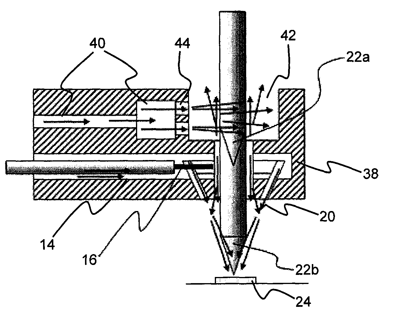
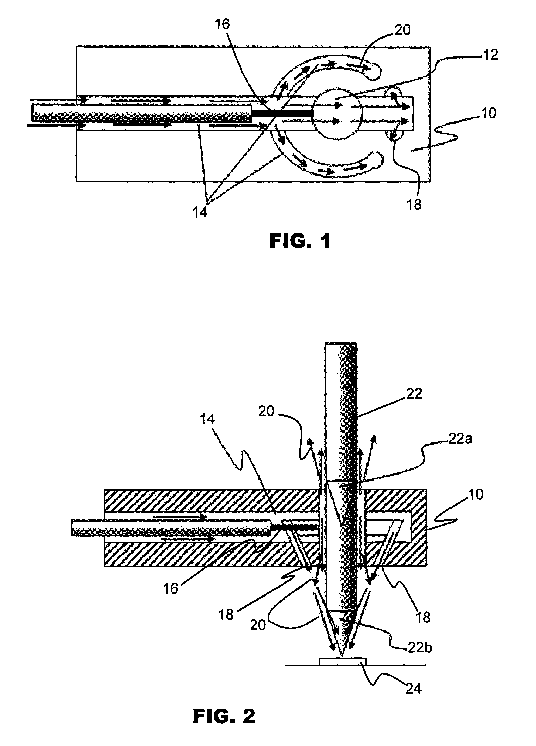
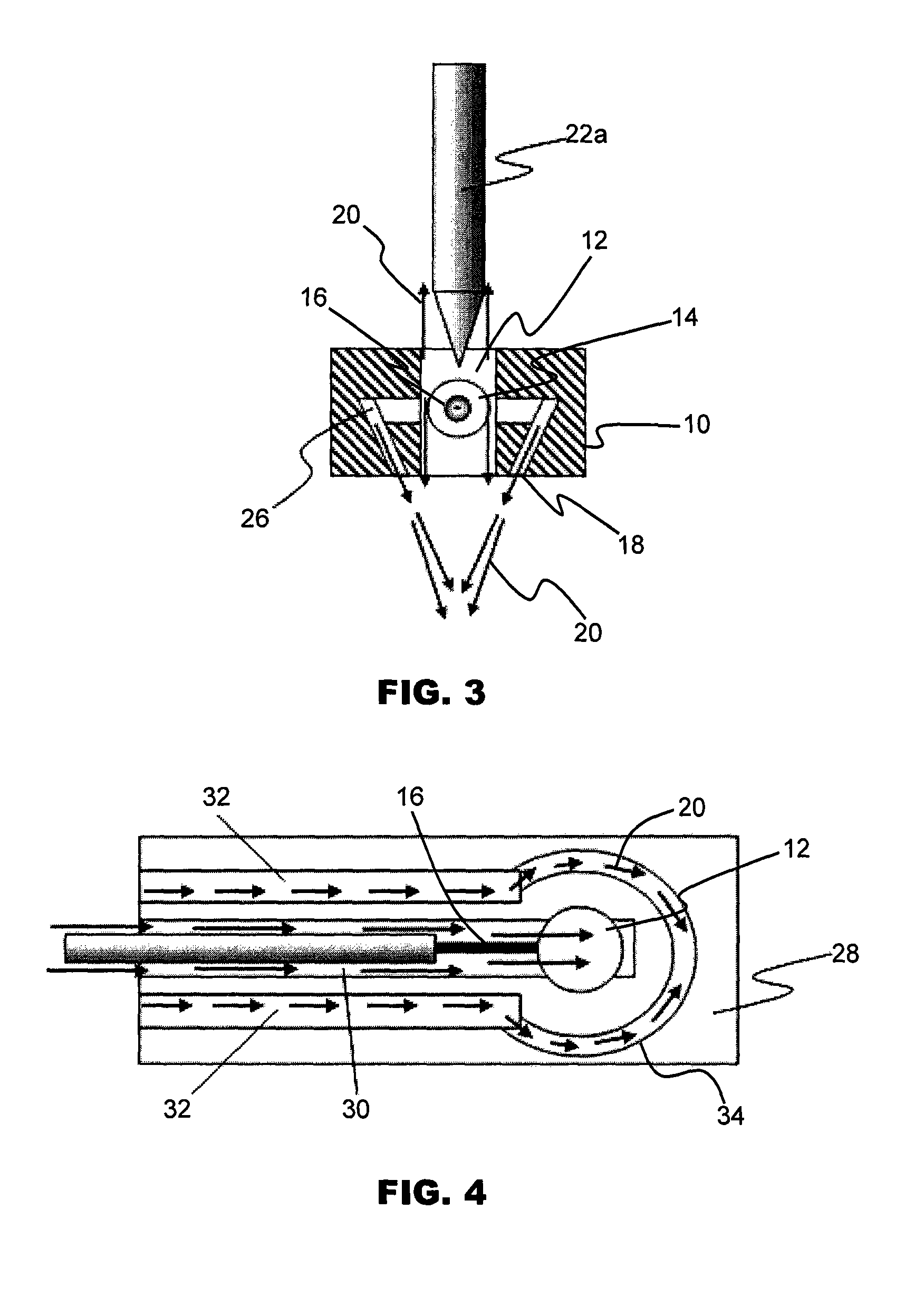
[0024]FIG. 1 is a sectional plan view of a gas supplying apparatus according to a first preferred embodiment of the invention illustrating its internal gas channels 14 for providing shielding gas during wire bonding of an electronic device. The gas supplying apparatus comprises a main body 10 having a through-hole 12 passing centrally through the main body, to which is connected a gas inlet which may be in the form of a network of internal gas channels 14. The gas channels 14 are located in the main body 10 and supply an inert gas 20, such as nitrogen gas or a mixture of hydrogen and nitrogen gas, to the region in and around the through-hole 12 and to gas outlets located adjacent to the through-hole 12.
[0025]FIG. 1 shows the network of gas channels 14 having three separate gas paths, one gas path leading directly to the through-hole 12 and two gas paths at least partially encircling the through-hole 12. Two gas nozzles 18 comprised in the gas outlets are located near or at an end of...
PUM
| Property | Measurement | Unit |
|---|---|---|
| Area | aaaaa | aaaaa |
Abstract
Description
Claims
Application Information