

Anodizing apparatus
a technology of anodizing apparatus and workpiece, which is applied in the direction of surface reaction electrolytic coating, solid separation, electrostatic separation, etc., can solve the problems of increasing the size of the treatment tank, limiting the accommodation space in the treatment tank, and unable to meet the needs of the user, so as to achieve effective anodizing treatment and increase the electrode area
- Summary
- Abstract
- Description
- Claims
- Application Information
AI Technical Summary
Benefits of technology
Problems solved by technology
Method used
Image

Examples
first embodiment
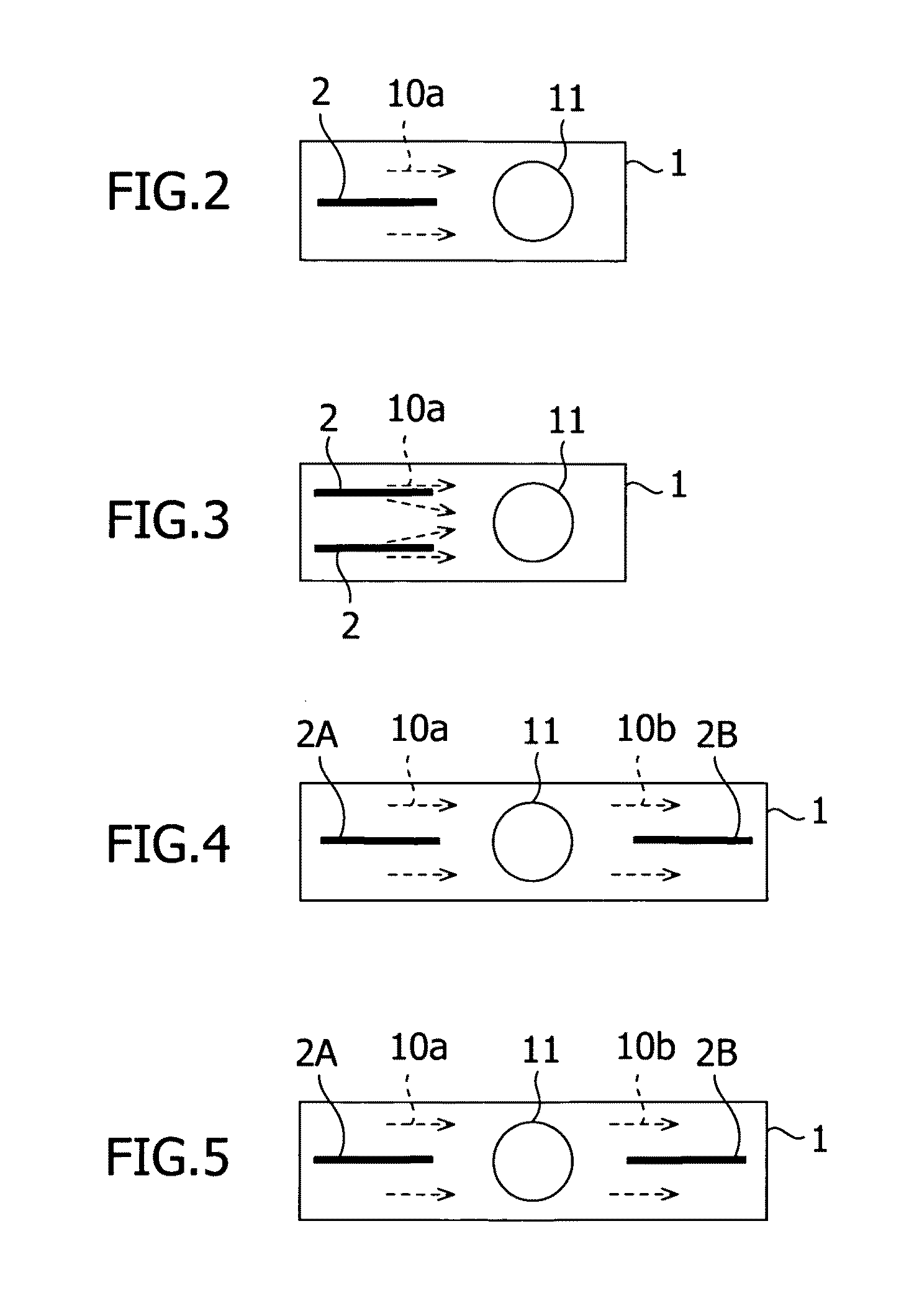
[0052]FIG. 2 is a schematic plan view showing a most basic first embodiment of a layout of the cathode plate in accordance with the present invention. In this embodiment, the cathode plate is oriented to the direction such as to cross the central axis of the workpiece 11 on one side of the workpiece 11. By this arrangement of the cathode plate 2, both surfaces of the cathode plate 2 can be utilized as a treatment electrode surface. Therefore, as compared with the conventional layout in which the cathode plate faces to the workpiece, the electrode area doubles even in the case in which comparison is made simply in terms of plane.
[0053]Moreover, the cathode plate 2 occupies only a portion corresponding to the thickness thereof of the side projected area of the workpiece 11, so that an agitating means (described later) for the treatment solution can be installed in spaces at both sides of the cathode plate 2 without hindering a path between the cathode plate 2 and the workpiece 11.
[005...
third embodiment
[0057]FIGS. 4 and 5 show a third embodiment in which two cathode plates 2A and 2B are disposed on both sides of the workpiece 11 with the workpiece 11 being held therebetween. In the mode shown in FIG. 4, there are generated flows 10a and 10b of treatment solution that are directed from both sides to the workpiece 11 along the two cathode plates 2A and 2B. In this case, the treatment solution arriving at the workpiece 11 is circulated to the upper part or the lower part (or both the side parts) of the treatment tank 1. On the other hand, in the mode shown in FIG. 5, there are generated flows 10a and 10b of treatment solution that are directed to the workpiece 11 along one cathode plate 2A, and flow along the other cathode plate 2B after passing through the workpiece 11.
fourth embodiment
[0058]Also, FIG. 6 shows a fourth embodiment in which a plurality of (four) cathode plates 2A and 2B are arranged in parallel so as to be separated from each other on both sides of the workpiece 11 with the workpiece 11 being held therebetween. In the case in which the cathode plates 2 are arranged in parallel on both sides of the workpiece 11 in this manner as well, there are a mode in which the flows 10a and 10b of treatment solution directed to the workpiece 11 are generated and a mode in which the flow 10a of treatment solution directed from one side of the treatment tank 1 to the other side thereof passing through the workpiece 11 is generated.
PUM
| Property | Measurement | Unit |
|---|---|---|
| surface area | aaaaa | aaaaa |
| voltage | aaaaa | aaaaa |
| voltage | aaaaa | aaaaa |
Abstract
Description
Claims
Application Information