
Highly reliable, low cost wind turbine rotor blade

a high-reliability, low-cost technology, applied in the direction of electric generator control, vessel construction, marine propulsion, etc., can solve the problems of low production efficiency, inconvenient high-volume blade manufacturing, and failure of current-technology wind turbine rotor blades, so as to reduce the width of the spar pultrusion base and improve bonding

Active Publication Date: 2012-06-05
PIASECKI AIRCRAFT CORP
View PDF25 Cites 15 Cited by
  • Summary
  • Abstract
  • Description
  • Claims
  • Application Information

AI Technical Summary

Benefits of technology

This approach results in lighter, more cost-effective rotor blades with inspectable joints, enabling superior quality control and reducing the likelihood of catastrophic failures by detecting defects during assembly rather than at operation.

Problems solved by technology

Wind turbines also are subject to frequent starting and stopping cycles.
Failure of current-technology wind turbine rotor blades is a very real problem for the wind power industry.
This non-automated prior art method of rotor blade construction is slow, imprecise, and not conducive of high-volume blade manufacture.
Prior art wind turbine rotor blade construction provides many opportunities for introduction of manufacturing defects, such as improper reduction in the number of the plys of glass fiber along the span of the blade or introduction of foreign object debris.
Prior art wind turbine rotor blade manufacture does not allow monitoring and correction of minor defects in internal blade components before those defects cause major blade failures.
The prior art method of blade manufacture also requires large and expensive tooling and highly skilled labor.
The prior art joints between the upper and lower spar caps and the upper and lower sides and between the spar caps and the shear web cannot be inspected once the upper and lower sides are bonded, preventing detection of defects.
A local defect, such as a void or defect in a bond for the shear web, can propagate along the length of the rotor blade during operation of the rotor blade, causing catastrophic failure.
The local defect generally will translate into a rotor blade failure triggered by a precipitating event, such as erosion, a lightning strike, a blade overload or a tower strike.
The root cause analysis concluded that factory processes and controls in the manufacturing environment of the prior art wind turbine rotor blades caused many of the failures.
Other failures were caused by design shortcomings of the prior art rotor blades.
Among the manufacturing defects found in the root cause analysis were dry fiber, misaligned fiber layup, core voids and deficient ply build-up in transition sections.
The prior art does not teach the wind turbine, the wind turbine rotor blade, or the method of the Invention.

Method used


Image

  • Highly reliable, low cost wind turbine rotor blade
  • Highly reliable, low cost wind turbine rotor blade
  • Highly reliable, low cost wind turbine rotor blade

Examples


Embodiment Construction

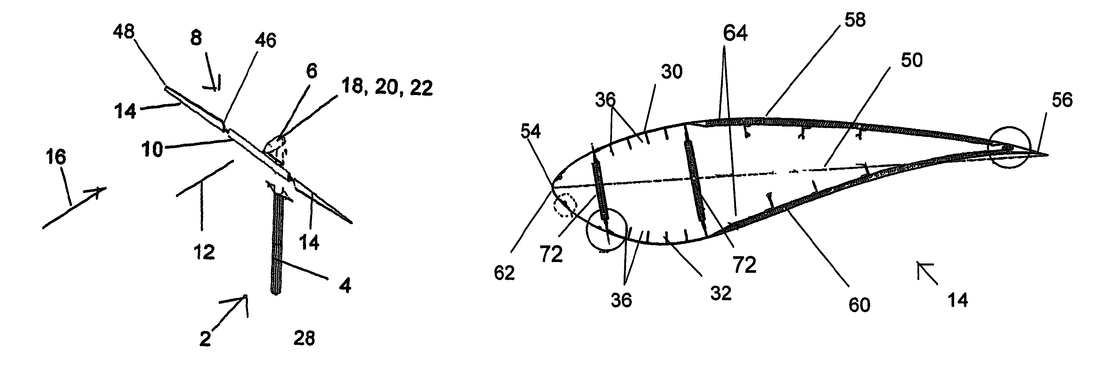
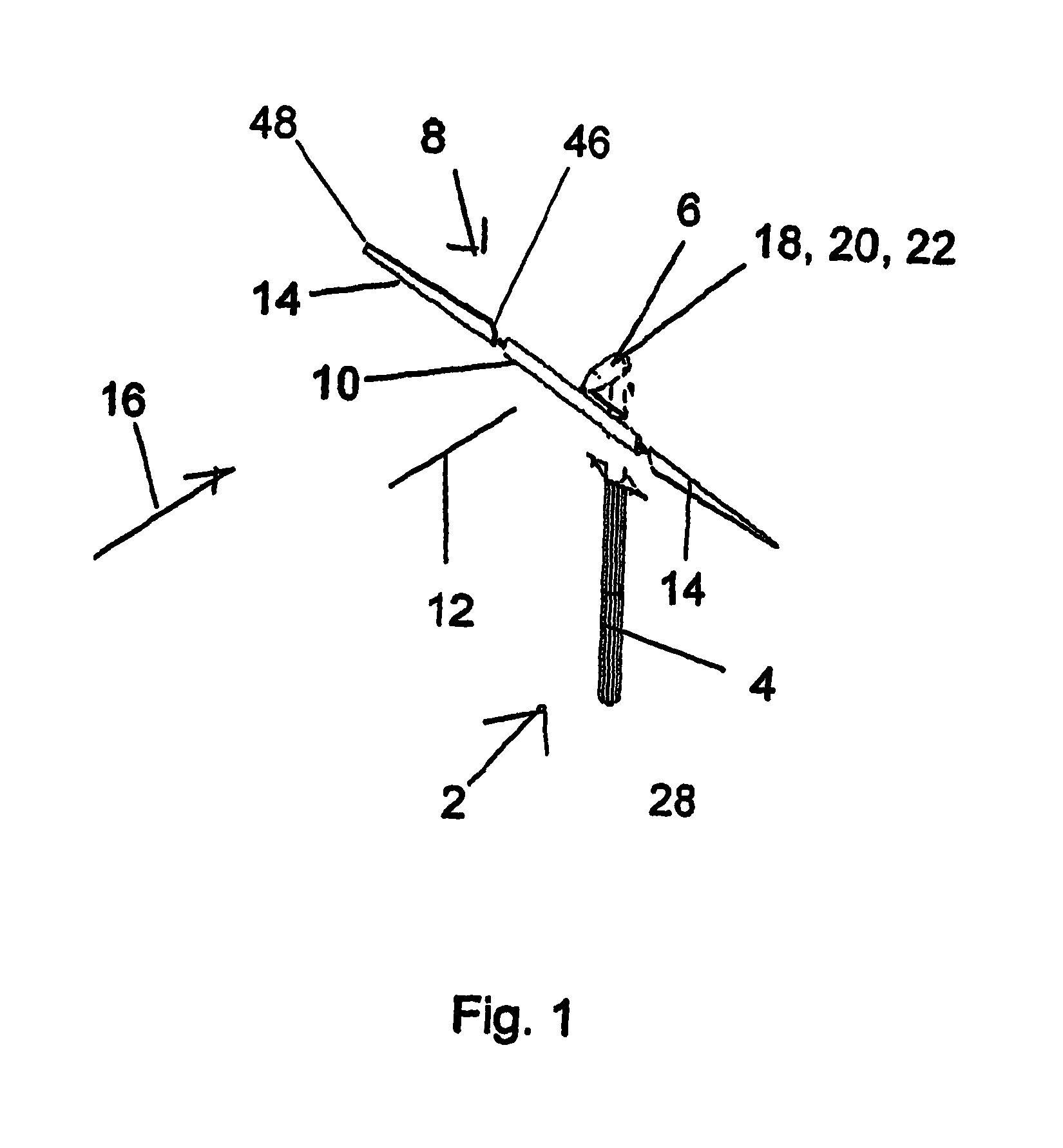
[0051]As shown by FIG. 1, the wind turbine 2 of the Invention features a tower 4 and a nacelle 6 supported by the tower 4. The nacelle supports a rotor 8. The rotor 8 comprises a hub beam 10 that rotates about an axis or rotation 12. The rotor 8 also includes two rotor blades 14 attached to opposing ends of the hub beam 10. The rotor blades 14 are in the shape of an airfoil and rotate about axis of rotation 12 in response to wind 16 flowing past the rotor blades 14. The nacelle 6 contains a low speed shaft 18 that is turned by the rotating rotor 8, a speed increaser 20 that is turned by the low speed shaft 18, and an electrical generator 22 that is turned by the speed increaser 20. Electrical generator 22 has an output that feeds electricity to an electrical load 24. The electrical generator 22 can be connected to an electrical power distribution grid 26 and the electrical load 24 can be a load 24 on the distribution grid 26. Tower 4 supports nacelle 6 above ground 28.

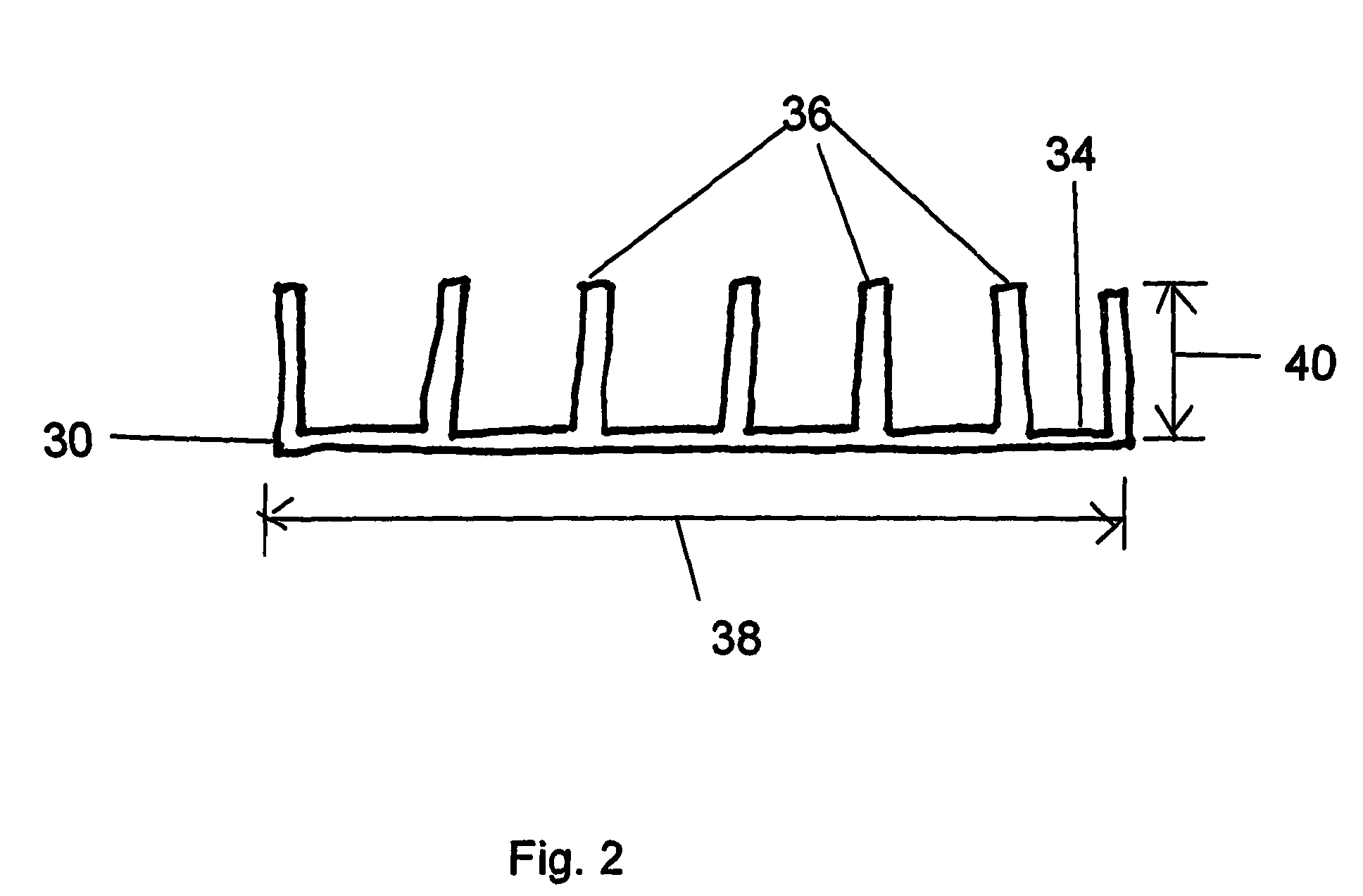
[0052]FIGS. 2 ...


PUM

PropertyMeasurementUnit
diameteraaaaaaaaaa
lengthaaaaaaaaaa
speedaaaaaaaaaa

Abstract

A wind turbine rotor blade and a wind turbine incorporating the rotor blade include a first and second composite skin. A first and a second spar pultrusion having a base and a plurality of integral ribs generally normal to the base are attached to the inside surface of the first and second composite skins and extend the span of the rotor blade. At least one shear web connects a rib of the first spar pultrusion to a corresponding rib of the second spar pultrusion. The width of the spar pultrusions decreases in a step-wise fashion along the span of the rotor blade from the root to the tip. The leading or trailing edge of the rotor blade may be selectably opened for inspection and repair.

Description

BACKGROUND OF THE INVENTION[0001]1. Field of the Invention[0002]The Invention is a wind turbine rotor blade assembly for generation of power and is a wind turbine featuring the blade. The Invention is also a method of making the wind turbine rotor blade. The wind turbine rotor blade of the invention is highly reliable and inexpensive to manufacture compared to large prior-technology wind turbine rotor blades.[0003]2. Description of the Related Art[0004]Wind turbines harvest the kinetic energy of the wind and convert that energy into shaft power at a rotating output shaft. The rotating output shaft turns an electrical generator to produce electrical power. For wind turbines of the horizontal type, the blades rotate in a plane of rotation that is on the upwind side or downwind side of a supporting tower and about an axis of rotation that is generally horizontal with the Earth. The rotor of a horizontal-type wind turbine for commercial electrical power generation is large, and can be o...

Claims


Application Information

Patent Timeline
Patent Type & Authority Patents(United States)
IPC IPC(8): B64C11/24
CPCB23P15/04F03D1/06F03D9/00Y02E10/721Y02E10/725Y02E10/728Y10T29/49337Y10T29/49339Y10T29/49336F03D13/20F03D9/25Y02E10/72
Inventor PIASECKI, FREDERICK W
Owner PIASECKI AIRCRAFT CORP
Learn More