Drive control circuit for polyphase motor capable of reducing variation among armature currents of respective phases, and spindle apparatus using the same

a technology of armature current and control circuit, which is applied in the direction of motor/generator/converter stopper, dynamo-electric converter control, instruments, etc., can solve the problems of increased cost and trouble, varied sine wave amplitudes passing through the u-, v- and w-phase armature windings,

Active Publication Date: 2012-06-12
NTN CORP
View PDF22 Cites 7 Cited by
  • Summary
  • Abstract
  • Description
  • Claims
  • Application Information

AI Technical Summary

Benefits of technology

[0019]According to the present invention, even when there is some degree of variation in the characteristics among the components of the drive control circuit and in the resistance among armature windings of the polyphase motor, variation among ultimate armature currents of respective phases can be reduced by adjusting the amplitude of current control signals by the amplitude adjusting circuit. Accordingly, the primary advantage of the present invention is that high-precision rotation control in which rotation fluctuation and vibration of the polyphase motor are suppressed can be performed.

Problems solved by technology

One cause of the rotation fluctuation and vibration may be that, in a three-phase motor, the amplitudes of sine waves passing through the U-, V-, and W-phase armature windings are varied and not uniform.
Accordingly, a plurality of these components must be prepared, whereby extra costs and trouble are required.

Method used


Image

  • Drive control circuit for polyphase motor capable of reducing variation among armature currents of respective phases, and spindle apparatus using the same
  • Drive control circuit for polyphase motor capable of reducing variation among armature currents of respective phases, and spindle apparatus using the same
  • Drive control circuit for polyphase motor capable of reducing variation among armature currents of respective phases, and spindle apparatus using the same

Examples


first embodiment

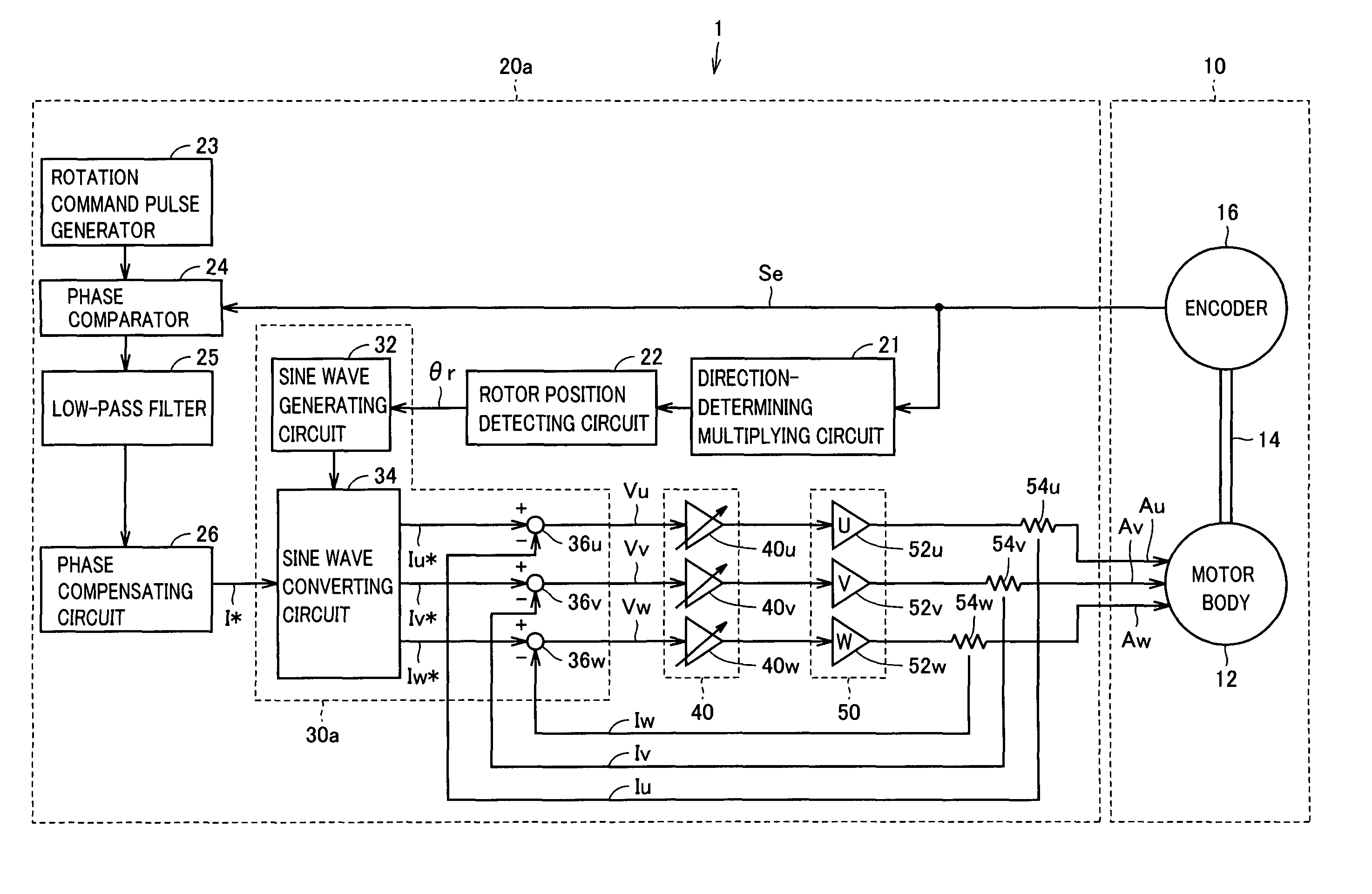
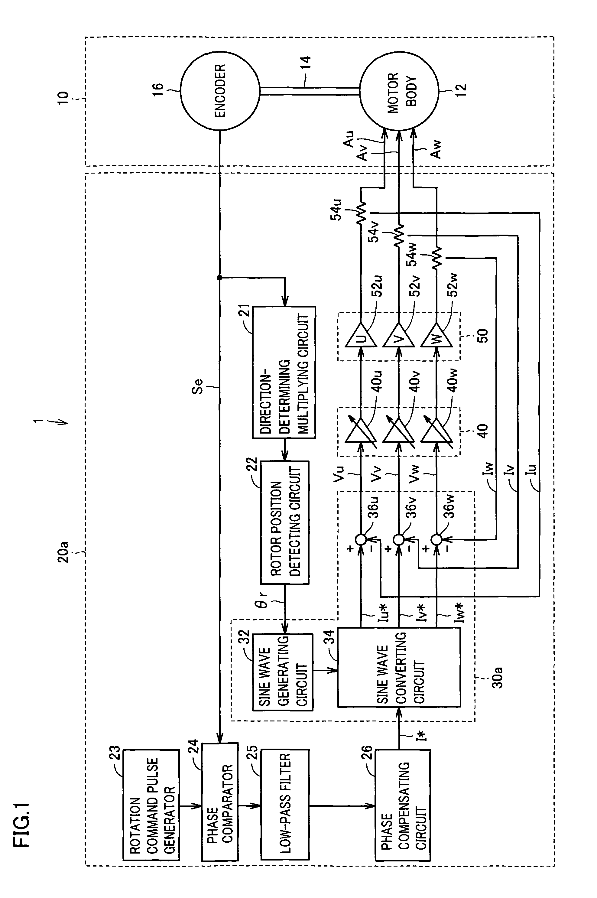
[0027]FIG. 1 is a block diagram showing a configuration of a spindle apparatus 1 of a first embodiment of the present invention. As shown in FIG. 1, spindle apparatus 1 includes a spindle motor 10, and a drive control circuit 20a that drives and controls spindle motor 10.

[0028]Spindle motor 10 includes a motor body 12, a spindle shaft 14 being the rotation shaft of motor body 12, and an encoder 16 fixed to spindle shaft 14. Motor body 12 in FIG. 1 is shown as a three-phase motor, as one exemplary polyphase motor of the present invention. The polyphase motors to which the present invention is applicable include brushless motors, synchronous motors, induction motors and the like.

[0029]Spindle shaft 14 is supported by bearings. When high rotation precision is required, as in a case of precision processing machines or precision inspection devices, spindle shaft 14 is supported in a noncontact manner using aerostatic bearings, so that friction resistance becomes substantially 0. Encoder ...

second embodiment

[0055]FIG. 4 is a block diagram showing a configuration of a spindle apparatus 3 of a second embodiment of the present invention. Spindle apparatus 3 shown in FIG. 4 performs position control using spindle motor 10, and for example, used as a motor for an actuator. Spindle apparatus 3 includes, similarly to the first embodiment shown in FIG. 1, spindle motor 10 and drive control circuit 60 therefor. It is different from the first embodiment of FIG. 1 in that, while in FIG. 1, rotation command pulse generator 23, phase comparator 24, low-pass filter 25 and phase compensating circuit 26 are used for PLL control, in FIG. 4, a position command pulse generator 61, a position comparator 62, a low-pass filter 63, a position compensating circuit 64, and a speed compensating circuit 65 are used instead.

[0056]In FIG. 4, position command pulse generator 61 provides position comparator 62 with a position command as a digital signal by the number of pulses. Position comparator 62 generates devia...


PUM


Abstract

Even when there is some degree of variation in the characteristics among components constituting a polyphase motor and a driving circuit therefor, current control signals of respective phases being input to the drive circuit have their amplitude finely adjusted by an amplitude control circuit, so that amplitude is uniform among armature currents of respective phases that are ultimately output from the drive circuit. The amplitude adjusting circuit is configured by gain variable amplifiers, for example. Thus, rotation fluctuation and vibration of the polyphase motor can be reduced.

Description

BACKGROUND OF THE INVENTION[0001]1. Field of the Invention[0002]The present invention relates to rotation control of a polyphase motor.[0003]2. Description of the Background Art[0004]A servo motor is used for high-precision rotation control and position control as a spindle motor used for audio devices and computer peripheral equipment (for example, see FIG. 3 of Japanese Patent Laying-Open No. 2007-074816). FIG. 5 is a block diagram schematically showing a configuration of a conventional spindle apparatus. In the following, referring to FIG. 5, the configuration of the conventional spindle apparatus is described.[0005]In FIG. 5, the spindle apparatus is configured by a spindle motor 131 and a drive control circuit 132 therefor. Spindle motor 131 includes a motor body 133 being a three-phase brushless motor, an encoder 134 fixed to the spindle shaft of motor body 133, and the like. Encoder 134 detects the rotation speed, rotor position and the like of motor body 133, and feeds back ...

Claims


Application Information

Patent Timeline
Patent Type & Authority Patents(United States)
IPC IPC(8): G05F1/10H02P6/06H02P6/08H02P6/10
CPCH02P6/10
Inventor AONO, KAZUYUKINAKAJIMA, AKIO
Owner NTN CORP
Why Eureka
Try Eureka