Flow elements for use with flexible spinal needles, needle assemblies for manufacture and methods therefor

a technology of flexible needles and flow elements, applied in the field of medical devices, can solve the problems of large needles and catheters, unacceptably high incidence of post-dural puncture headaches, and severe limitations in the usefulness of continuous spinal techniques, and achieve the effects of preventing, or minimizing, the extent of the effect of flexible needles

Active Publication Date: 2012-06-19
CUSTOM MEDICAL APPL
View PDF82 Cites 2 Cited by
  • Summary
  • Abstract
  • Description
  • Claims
  • Application Information

AI Technical Summary

Benefits of technology

[0012]In order to improve the performance of a flexible needle, a flow element is provided for use in conjunction with the flexible needle. A flow element may be used with flexible needles, including flexible spinal needles, and flexible needle assemblies to prevent, or at least minimize, the extent to which flow occlusion may occur within a flexible needle, particularly when used with a flexible needle for minimizing incidence of post-dural puncture headache. The flow element includes a body having an internal flow path for conducting a fluid through a flexible needle and an anti-restriction member. The anti-restriction member includes an elongated body, a proximal end element coupled to the body within the internal flow path, and a distal end element for positioning at least a portion of the elongated body within a flexible needle.
[0013]In certain embodiments, a parallel flexible spinal needle assembly for minimizing flow occlusion through an internal flow path of a flexible needle, caused by unintended kinking potentially resultant from ligament or muscle layer movements, is also provided.

Problems solved by technology

Unfortunately, technical problems have severely limited the usefulness of continuous spinal techniques.
Until recently, the standard technique of inserting the spinal catheter through the spinal needle, coupled with the difficulty of manufacturing truly small needles and catheters, has meant large needles and catheters were required.
This in turn has resulted in an unacceptably high incidence of post-dural puncture headaches (“PDPH”).
Unfortunately, these catheters proved difficult to handle and to make.
Moreover, such catheters were expensive, and, more ominously, they were associated with several reports of neurologic damage (i.e., cauda equina syndrome).
Many clinicians experimented with these catheters and subsequently abandoned them.
The FDA's decision to recall and ban the marketing of microspinal catheters for CSA in the U.S., and its requirement that any new device for CSA be subjected to an extremely stringent pre-market approval process, have resulted in a freeze on the development of these products, at least in the United States.
Nevertheless, the use of such catheters for injecting local anesthetics for the establishing surgical anesthesia is not the only use to which such devices might beneficially be put.
Installing a conventional catheter generally requires several cumbersome steps involving threading long, very thin catheters through a spinal needle.
Simply threading a catheter into the end of a spinal needle can be so difficult that some manufacturers include a “threading aid” as part of their kit.
In short, the conventional spinal catheter threading operation requires considerable time and effort on the part of a clinician.
Once threaded, a degree of uncertainty exists for the clinician as to how far to insert the catheter.
Also, a risk exists that a piece of the catheter might be sheared off by the needle, if the catheter were to be pulled back during the threading operation.
In such cases, bits of catheter could potentially be left behind in the intrathecal space.
Furthermore, removing the spinal needle, while holding the catheter in position, can be a challenge.
Additionally, attaching a hub / injection adapter to the naked end of the 28 gauge or 32 gauge catheter can be even more of a challenge.
One problem of Sprotte and Whitacre non-cutting spinal needles is that the injection orifice is on the side of the needle.
Failures in spinal anesthesia administration have been known to occur when the needle was “half-in, half-out” of the intrathecal space, i.e. the needle was only partially inserted into the intrathecal space.
Another problem with Sprotte and Whitacre spinal needles is that the smooth curved tip profile provides no definitive feedback signal or “click” to the clinician when the dura is punctured.
This lack of feedback contributes to uncertainty in catheter tip placement for the clinician.

Method used


Image

  • Flow elements for use with flexible spinal needles, needle assemblies for manufacture and methods therefor
  • Flow elements for use with flexible spinal needles, needle assemblies for manufacture and methods therefor
  • Flow elements for use with flexible spinal needles, needle assemblies for manufacture and methods therefor

Examples


Embodiment Construction

[0053]The illustrations presented herein are, in some instances, not actual views of any particular flow element, flexible needle assembly or other feature of a flexible spinal needle assembly, but are merely idealized representation that are employed to describe the invention. Additionally, elements common between figures may retain the same numerical designation.

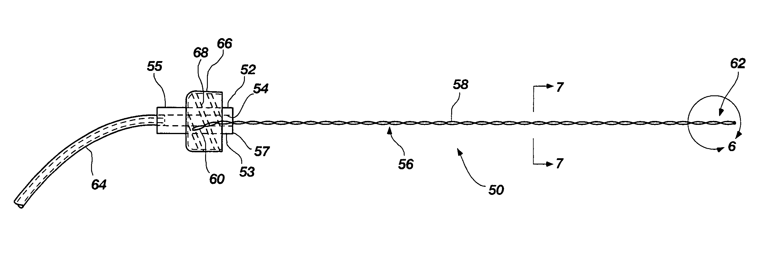
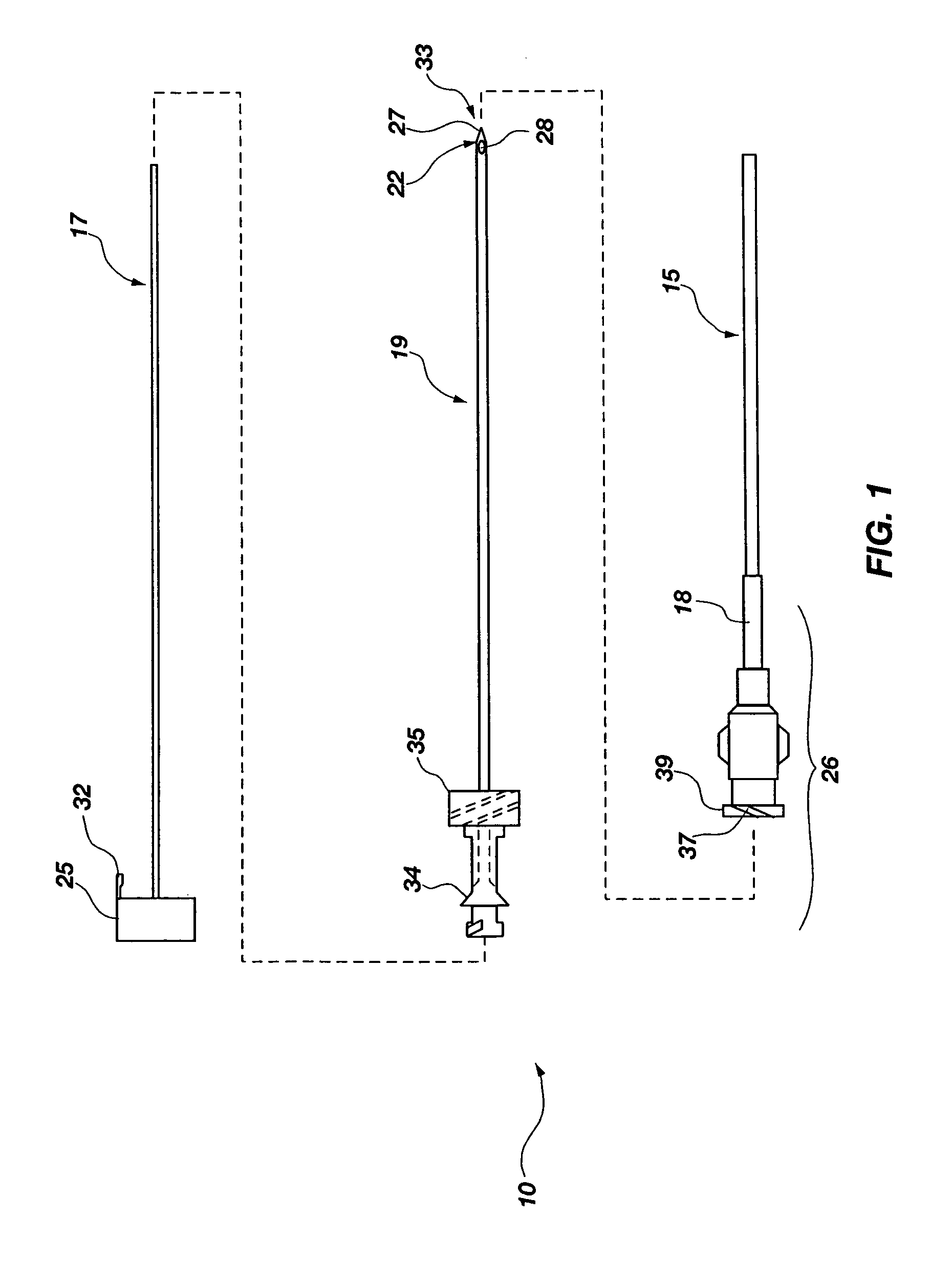
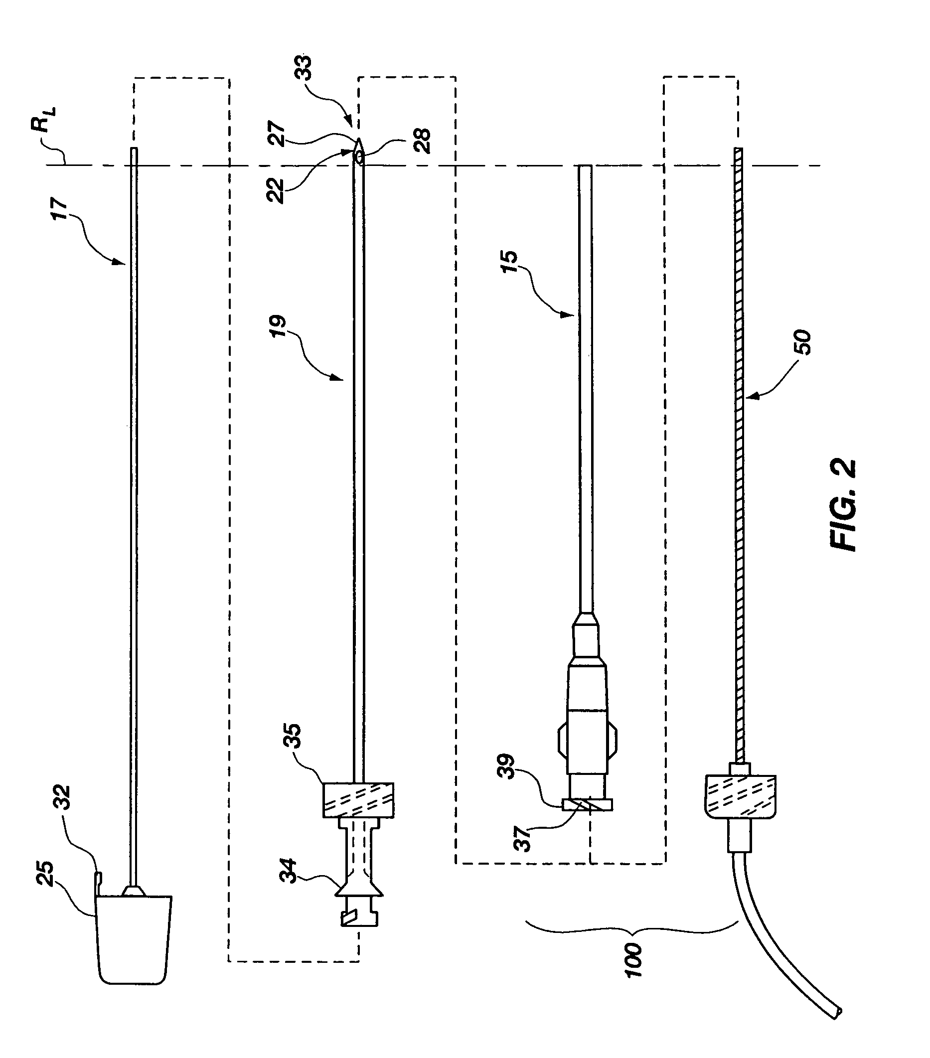
[0054]Generally, the flow element may be advantageously used with an integrated spinal needle or flexible needle assembly 10 (much like an intravenous needle and catheter mounted therein) as shown in FIG. 1, with the flexible needle 15 being releasably mounted on the outside of a support needle 19. The flexible needle 15 is configured for uses with embodiments of the invention as will be further described below. Flexible needle 15, being configured for placement on the outside of the support needle 19, provides a number of advantages which are first described hereafter, prior to turning to the embodiments of the invention....


PUM

PropertyMeasurementUnit
angleaaaaaaaaaa
flexibleaaaaaaaaaa
outer diameteraaaaaaaaaa

Abstract

A flow element (50) for use with flexible needles and flexible needle assemblies (10) to minimize flow occlusion within a flexible needle (15) is provided. The flow element (50) is particularly suited for uses with a flexible needle (15) for minimizing incidence of post-dural puncture headache. The flow element (50) includes a body having an internal flow path for conducting a fluid through a flexible needle, and an anti-restriction member (56). The anti-restriction member (56) includes an elongated body (58), a proximal end (70) coupled to the body within the internal flow path, and a distal end (60) for positioning at least a portion of the elongated body within a flexible needle. A flexible spinal needle assembly (10) for minimizing flow occlusion through an internal flow path of a flexible needle (15) by unintended kinking that is potentially caused by ligament or muscle layer movements is also provided, hi other embodiments, a flexible spinal needle assembly (10), a flexible spinal needle assembly kit, a method for installing a flexible spinal needle assembly, and a process for producing a flow element are provided.

Description

CROSS-REFERENCE TO RELATED APPLICATIONS[0001]This is a national phase entry under 35 U.S.C. §371 of International Patent Application PCT / US2009 / 000250, filed Jan. 14, 2009, published in English as International Patent Publication WO 2009 / 091567 A2 on Jul. 23, 2009, which claims the benefit under 35 U.S.C. §119(e) to U.S. Provisional Patent Application Ser. No. 61 / 020,791, filed Jan. 14, 2008.TECHNICAL FIELD[0002]This invention relates generally to medical devices, and particularly to structures for preventing fluid occlusion in medical needles. It is particularly directed to a flow element for use with flexible needles and flexible spinal needle assemblies, including methods for manufacture and use thereof.BACKGROUND[0003]The advantages of continuous administration of spinal anesthesia have long been appreciated by anesthesiologists. Unlike conventional single-shot techniques, continuous spinal anesthesia (“CSA”) with an indwelling catheter facilitates the administration of anesthes...

Claims


Application Information

Patent Timeline
Patent Type & Authority Patents(United States)
IPC IPC(8): A61M5/32
CPCA61B17/3401Y10T29/49826A61M5/329
Inventor RACZ, N. SANDOR
Owner CUSTOM MEDICAL APPL
Why Eureka
Try Eureka