
Introducer sheath with adhesive attachment means and a rotating side tube

a technology of adhesive attachment and introducer sheath, which is applied in the direction of catheters, other medical devices, infusion needles, etc., can solve the problems of hemostasis valve slipping off of the pad, the suture for retention of the introducer sheath requires about 2 minutes of time for the operator, and the hemostasis valve can be easily removed. , to achieve the effect of quick attachment and detachment, and facilitate rapid attachment and detachmen

Active Publication Date: 2012-06-26
FISCHELL INNOVATIONS
View PDF5 Cites 11 Cited by
  • Summary
  • Abstract
  • Description
  • Claims
  • Application Information

AI Technical Summary

Benefits of technology

"The present invention provides a new way to attach an introducer sheath to a patient's skin without using a separate adhesive pad or suture. This is done by using a flexible adhesive pad that is attached to the sheath's hemostasis valve. This adhesive pad has a removable cover sheet that is removed to expose the adhesive surface and quickly attach the sheath to the skin. The adhesive pad is designed to be easily gripped by the operator and allows the sheath to be positioned at an optimal location on the patient's skin. The invention also eliminates the need for a separate adhesive pad and suture, reducing discomfort for the patient and the risk of infection. The adhesive pad is securely attached to the sheath and allows for rotation of the hemostasis valve and side tube connected to it."

Problems solved by technology

It is believed that suturing for retention of the sheath requires about 2 minutes of time for the operator.
Furthermore, removing the suture could again take about 2 minutes compared to removing the pressure sensitive adhesive pad that would probably take less than 2 seconds to accomplish.
Also, using a separate adhesive pad there is always the possibility that the hemostasis valve will slip off of the pad when there is a considerable force exerted on the separate pad when a catheter is pushed into or pulled out of the hemostasis valve.

Method used


Image

  • Introducer sheath with adhesive attachment means and a rotating side tube
  • Introducer sheath with adhesive attachment means and a rotating side tube
  • Introducer sheath with adhesive attachment means and a rotating side tube

Examples


Embodiment Construction

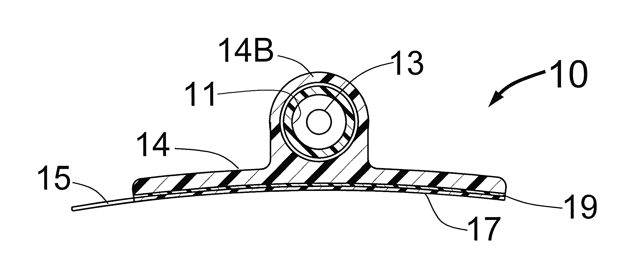
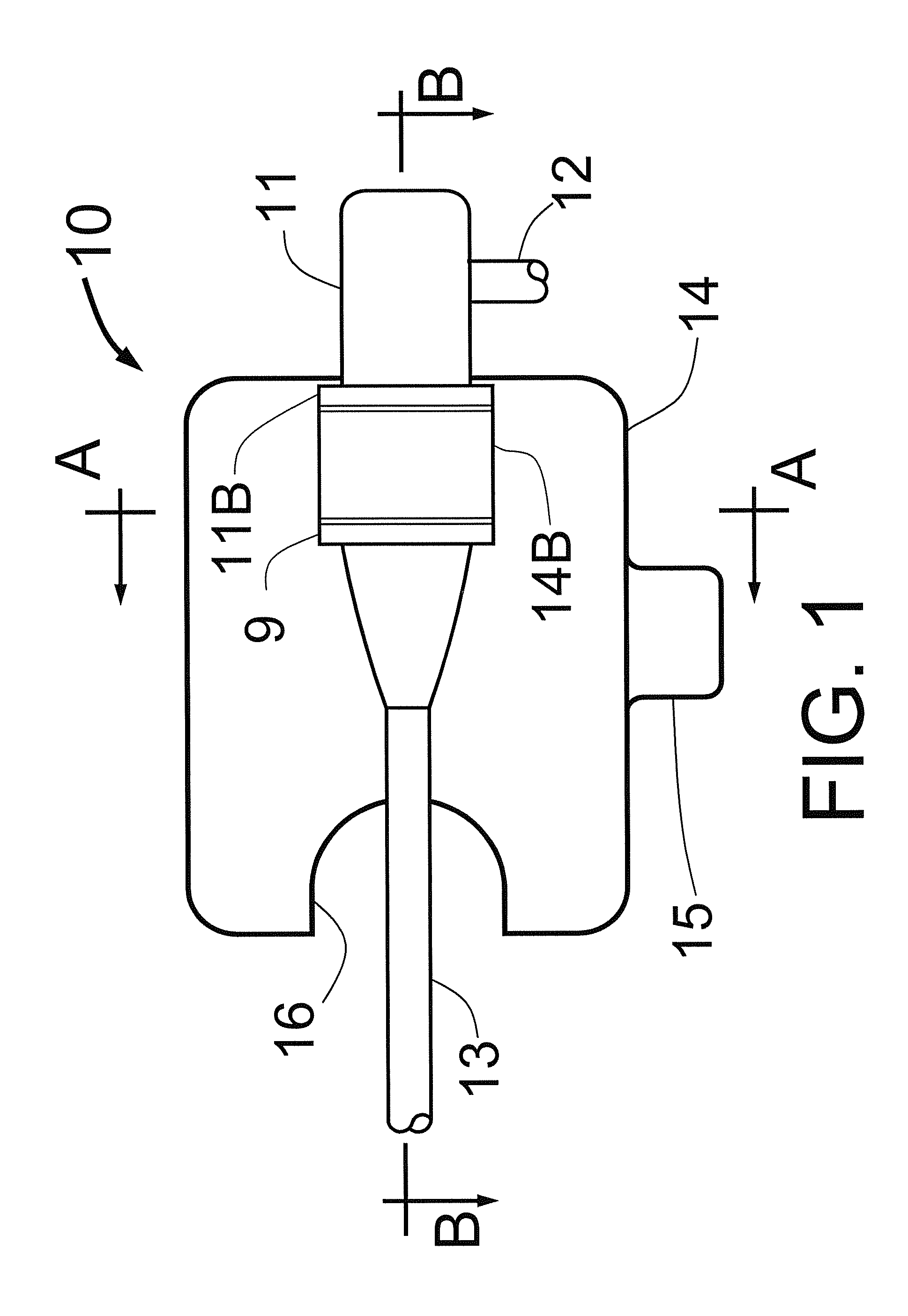
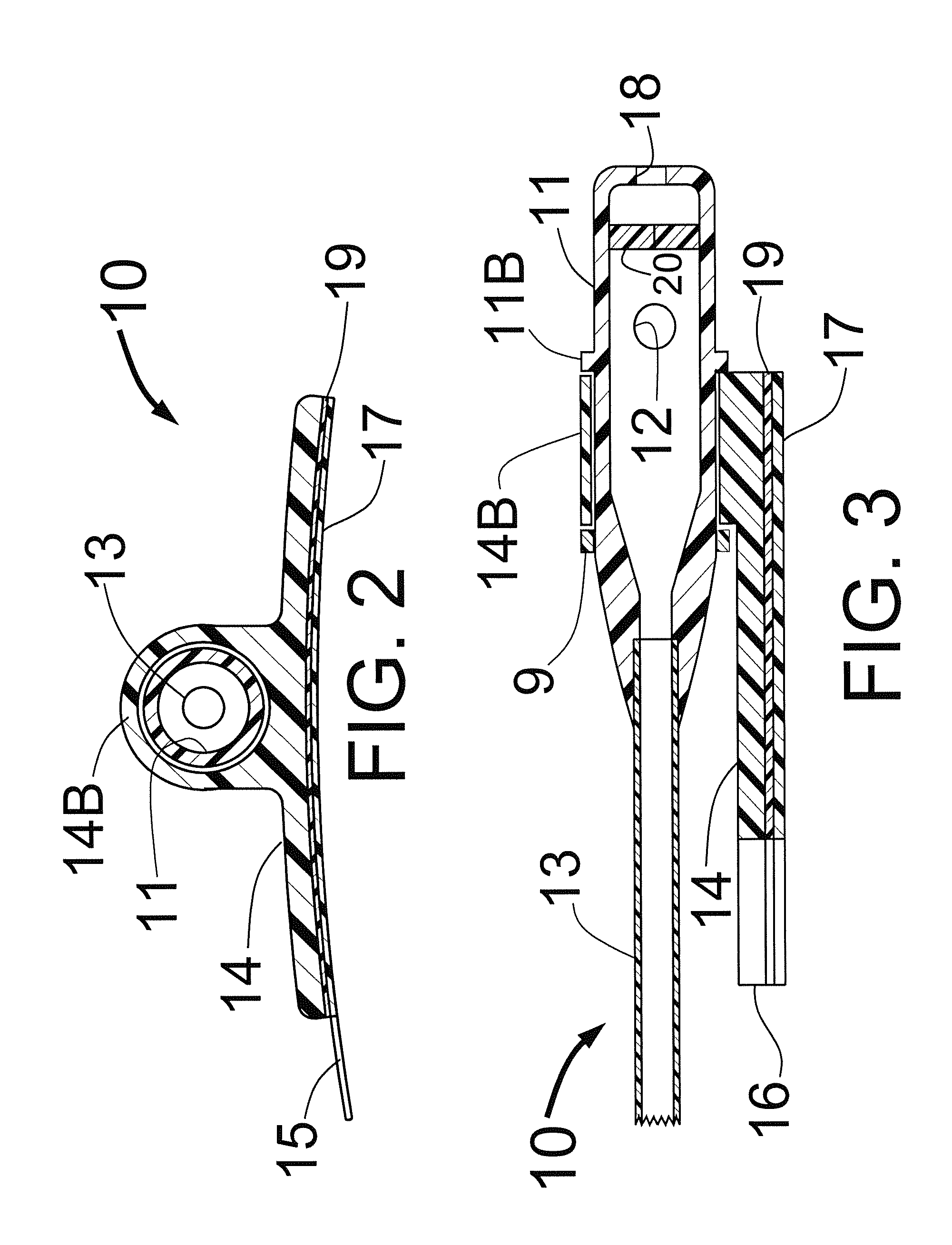
[0017]FIG. 1 is a top view of the present invention showing a proximal portion of an introducer sheath 10 that has a hemostasis valve 11 located at the sheath's proximal end. The hemostasis valve 11 has a side tube 12 that is used to flush the sheath with normal saline solution and to inject various medications as needed to treat the patient. At the distal end of the hemostasis valve 11 is the shaft 13 that is placed into the patient's vascular system for introducing various catheters. The flexible adhesive pad 14 has a cylindrical portion 14B within which the hemostasis valve 11 and its attached side tube 12 are free to rotate. The shoulder 11B of the hemostasis valve 11 and the slip-on-ring 9 surround the cylindrical portion 14B of the adhesive pad 14 to prevent that cylindrical portion 14B from coming off of the hemostasis valve 11. The adhesive pad 14, has a thin layer of pressure sensitive adhesive 19 as shown in FIGS. 2 and 3. As shown in FIGS. 1, 2 and 3, the tab 15 is used t...


PUM


Abstract

The present invention is an introducer sheath that is improved by having an adhesive pad located near the sheath's proximal end that detachably attaches the introducer sheath to the patient's skin without requiring any additional parts that come from a separate sterile package such as a needle and a suture or a separate adhesive pad. The present invention also teaches a means to rotatingly connect the adhesive pad to the sheath's hemostasis valve so that the proximal portion of the hemostasis valve is free to rotate about the adhesive pad even after the adhesive pad is firmly attached to the patient's skin. This design allows the operator to position the side tube that is connected to the hemostasis valve at an optimum location relative to the patient's skin.

Description

FIELD OF THE INVENTION[0001]This invention is in the field of devices to assist in the placement of catheters through the skin to treat certain coronary and peripheral vascular disorders.BACKGROUND OF THE INVENTION[0002]At the present time, physicians place an introducer sheath through the skin of a patient to access that patient's vascular system. Two usual places to gain access are through the skin at the groin to enter the femoral artery and through the skin in the wrist to access the radial artery. After the introducer sheath is placed through the skin, the physician will typically use a suture to fasten the proximal end of the introducer sheath to the patient's skin. That process requires the opening of an additional package that contains the suture thread and a needle, and also requires skin penetration that can be somewhat painful for the patient and has the possibility of infection.[0003]In U.S. Pat. No. 5,827,239, S. F. Bierman has shown an adhesive attachment to the skin o...

Claims


Application Information

Patent Timeline
Patent Type & Authority Patents(United States)
IPC IPC(8): A61M5/178A61M5/32
CPCA61M25/02A61M25/0662A61M39/0606A61M2025/0266A61M2025/0273A61M2025/028A61M2039/062
Inventor FISCHELL, ROBERT E.
Owner FISCHELL INNOVATIONS
Learn More