Receiver

a receiver and receiver technology, applied in the field of receivers, can solve the problems of large area on the circuit board, inability to fully integrate automatic gain control (agc), and inability to control the so-called offset voltage, etc., and achieve the effect of facilitating the circuit design of the receiver

Active Publication Date: 2012-06-26
NOKIA TECHNOLOGLES OY
View PDF20 Cites 0 Cited by
  • Summary
  • Abstract
  • Description
  • Claims
  • Application Information

AI Technical Summary

Benefits of technology

[0024]The embodiments of the invention may facilitate receiver circuitry design that can be implemented in a lesser silicon area than typical prior art circuits. The embodiments may also enable common gain entity for different frequencies without necessitating use of discrete components for these functions. Thus the embodiments may enable a fully integrated automatic gain control (AGC).

Problems solved by technology

These components require a substantially large area on a circuit board.
A problem that is faced when implementing a direct conversion receiver is the control of the so called offset voltage.
In direct conversion receivers the variation in the direct current (DC) level causes problems because the DC cannot be amplified with the same gain as the desired signal.
Because of the requirement for substantially large capacitors a fully integrated automatic gain control (AGC) has not been considered as a viable possibility.
In the modern receivers the complexity and size of the radio parts has also increased because a receiving terminal may need to be able to handle an increased number of operation bands and / or modes.
The DC-voltage variation cannot be amplified since it would cause wrong biasing in the baseband and most likely phenomenon known as clipping in the analog to digital converter (ADC).

Method used


Image

  • Receiver
  • Receiver
  • Receiver

Examples


Embodiment Construction

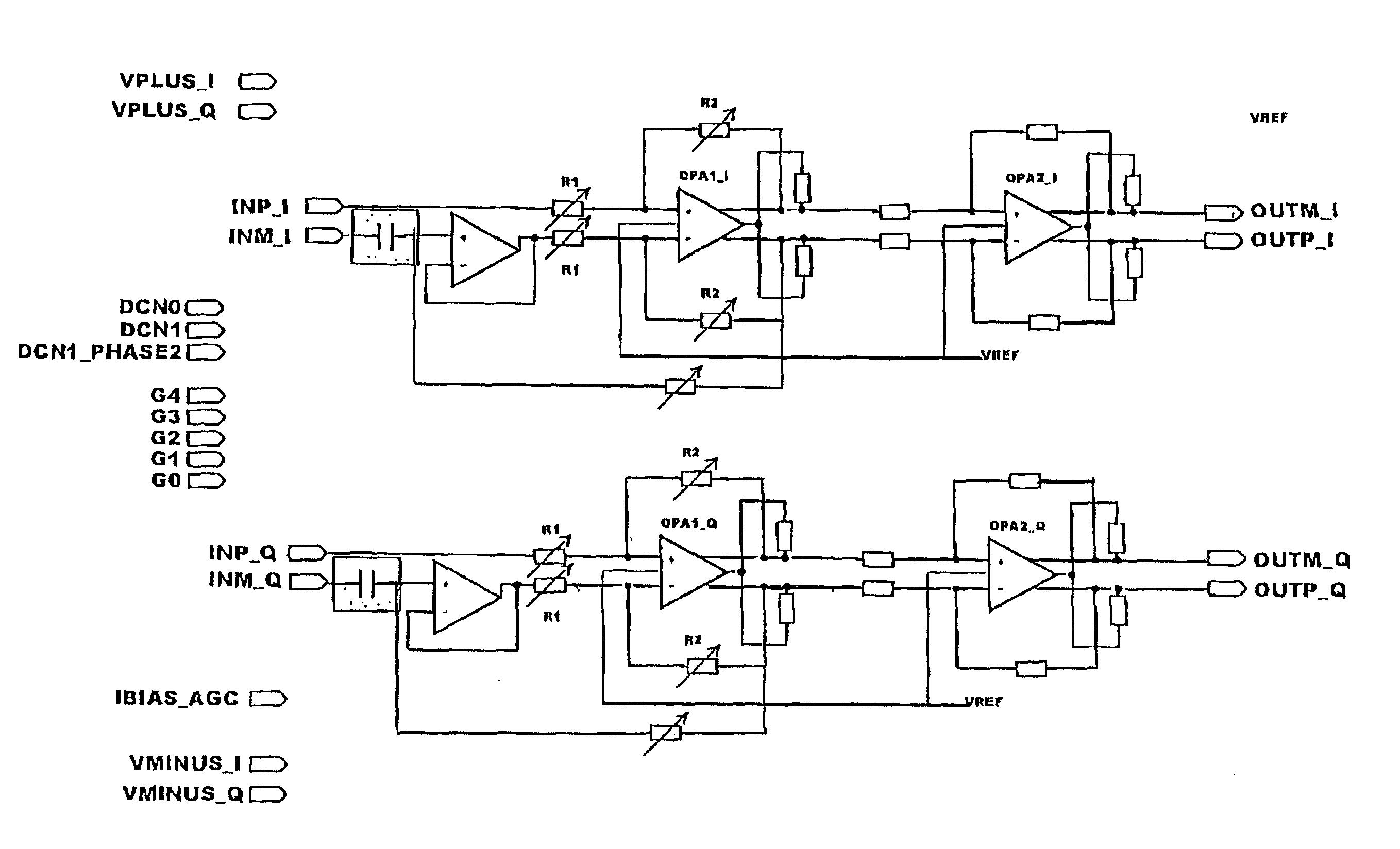
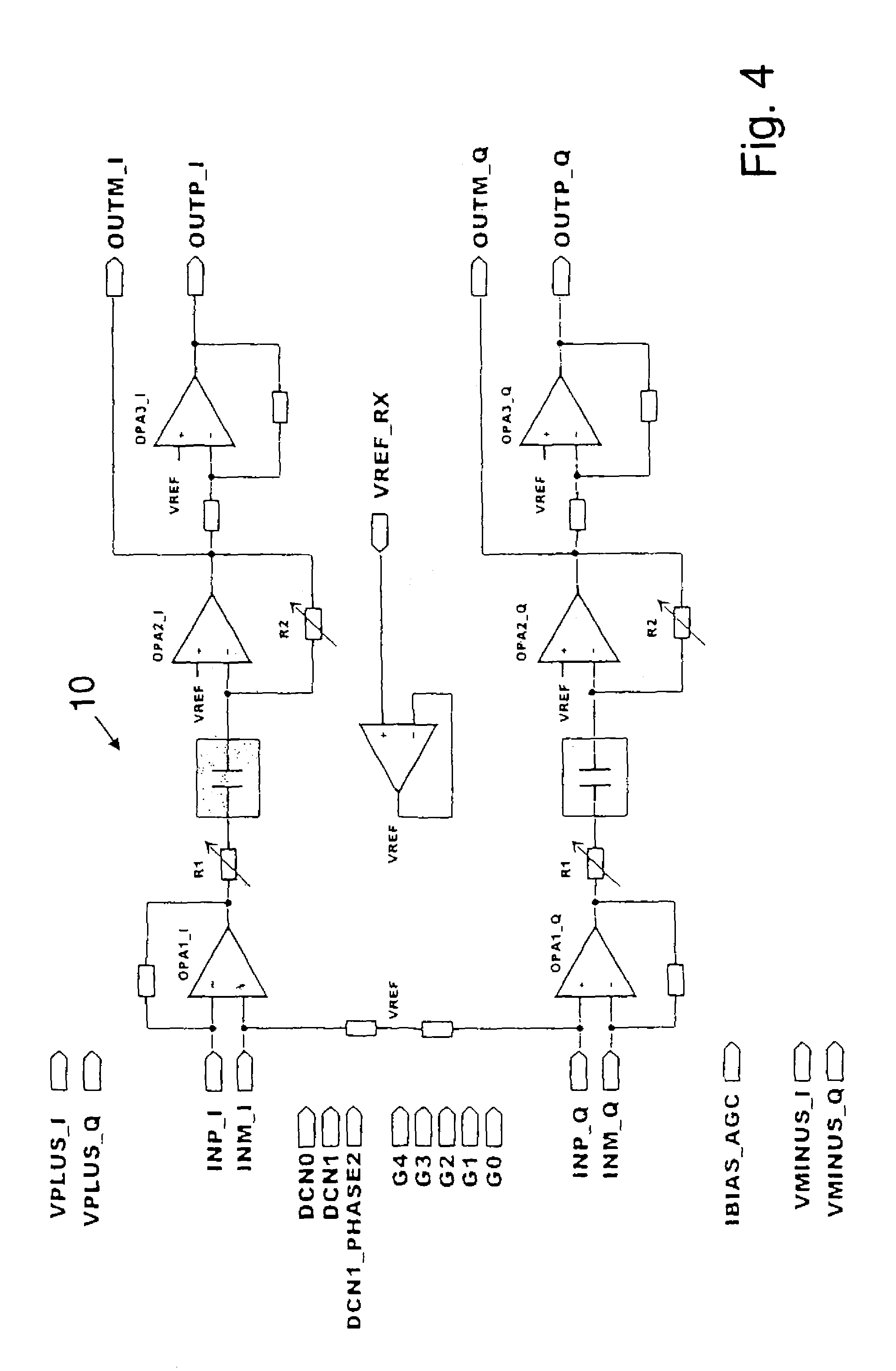
[0035]A circuit 10 for a receiver embodying a common multimode automatic gain control (AGC) function in accordance with the principles of the present invention is shown in FIG. 4. The circuit is arranged such that the DC level of the output (OUTP_I, OUTP_Q) of the circuit 10 can be fixed regardless of the DC level at the input (INP_I, INP_Q) of the circuit.

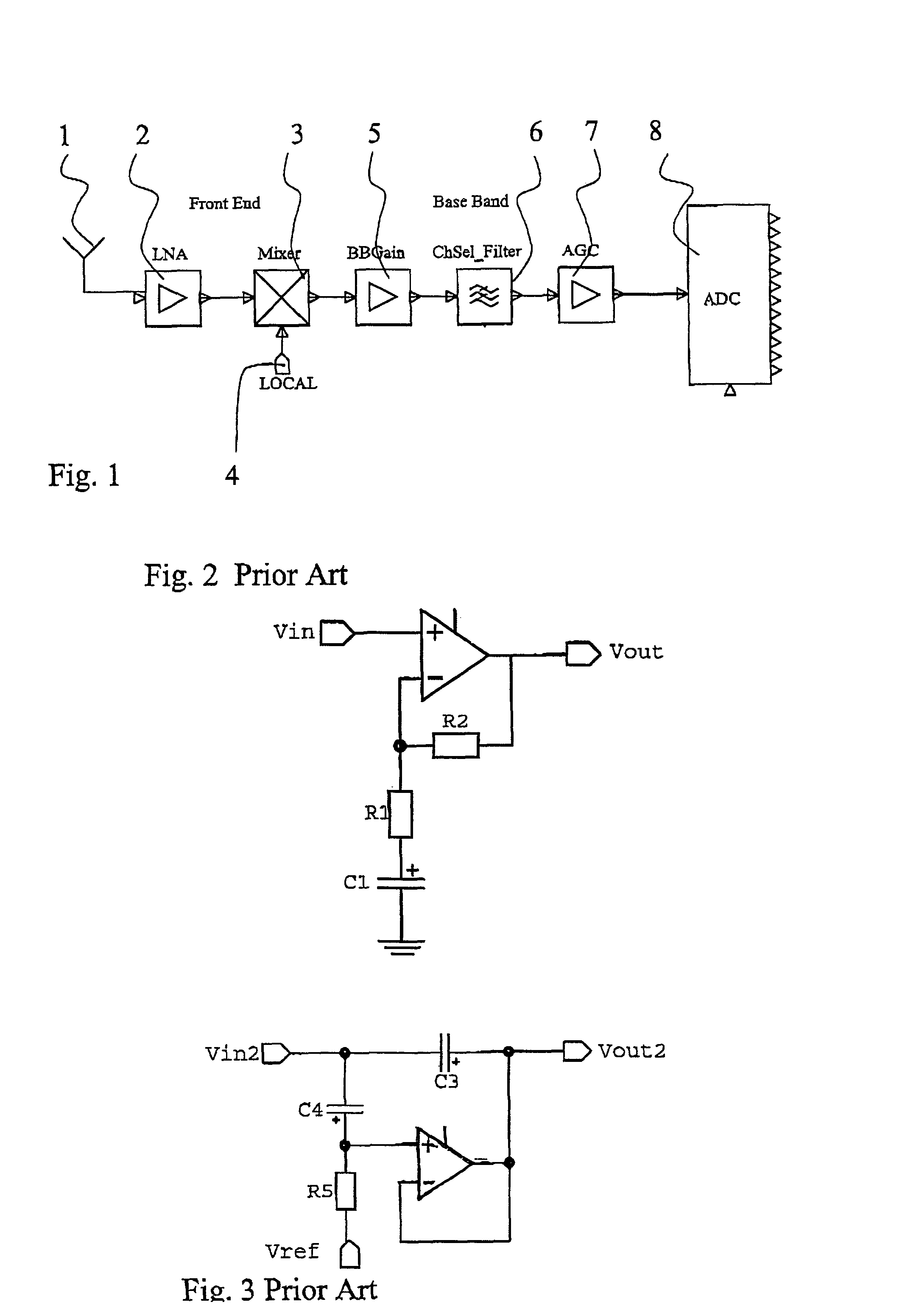
[0036]FIG. 5 illustrates a circuit 11 that may be used in the FIG. 4 circuit arrangement 10. The circuit 11 comprises a capacitor C1 and a resistor R1 on signal path between the input Vin and an input 21 of an operational amplifier (opamp) 12. Capacitor C1 and the resistor R1 are for defining the high pass filter function of the circuit 11. More particularly, capacitor C1 is for defining the lowpass cut-off frequency of the circuit. Resistors R1 and a second resistor R2 together define the gain of the circuit 11.

[0037]The operational amplifier 12 is controlled by a reference signal. The reference signal is fed in another input 22 ...


PUM


Abstract

A receiver and a method for a receiver is disclosed. The receiver comprises a signal processing path for receiving a first signal modulated by a first modulation method and having a first bandwidth and a second signal modulated by a second modulation method and having a second bandwidth. A common gain control function is provided for processing said first and second signals. A common DC offset cancellation is also provided for said first and second signals. In a preferred embodiment the gain control and the DC offset cancellation a provided by a single circuit.

Description

FIELD OF THE INVENTION[0001]The present invention relates to a receiver and more particularly to processing of signals in a receiver.BACKGROUND OF THE INVENTION[0002]In a typical wireless communication system a receiver part of a receiving station receives radio frequency (RF) signals that have been generated and transmitted by a transmitting station. When a signal is received at the receiving station the radio frequency signal is typically down-converted from the radio frequency to baseband frequency. In a so called direct conversion receiver the radio frequency signal is converted directly to a baseband signal without converting the incoming signal first to one or several intermediate frequencies (IF). Hence the direct conversion receivers are sometimes referred to as zero intermediate frequency receivers.[0003]FIG. 1 shows a block chart for a signal path in a receiver. In a typical multi-frequency band and multi-system direct conversion receiver a radio frequency (RF) signal is o...

Claims


Application Information

Patent Timeline
Patent Type & Authority Patents(United States)
IPC IPC(8): H04L27/08H04L25/06H04L23/00H04B7/00H03D3/00H04B1/30
CPCH03D3/008H03F3/45475H04B1/30H03F2203/45212
Inventor VILHONEN, SAMI
Owner NOKIA TECHNOLOGLES OY
Why Eureka
Try Eureka