
Vehicle windshield wiper system

a technology for windshield wipers and vehicles, applied in vehicle maintenance, vehicle cleaning, roofs, etc., can solve the problem of significant design problems of vehicle bodies, and achieve the effect of minimizing the protrusion of the engine room and efficient utilization

Inactive Publication Date: 2012-07-03
MITSUBA CORP
View PDF8 Cites 5 Cited by
  • Summary
  • Abstract
  • Description
  • Claims
  • Application Information

AI Technical Summary

Benefits of technology

The compact design minimizes the lateral width and fore-and-aft dimensions of the wiper system, allowing it to be installed in a narrower space under the windshield without compromising the vehicle body design, thus maximizing engine room space and reducing protrusion.

Problems solved by technology

Because the crank arm and link mechanism undergo relatively large displacements in operation, a relatively large space is required in a lower part of the recess, and this creates a significant problem in the design of the vehicle body.

Method used


Image

  • Vehicle windshield wiper system
  • Vehicle windshield wiper system
  • Vehicle windshield wiper system

Examples


Embodiment Construction

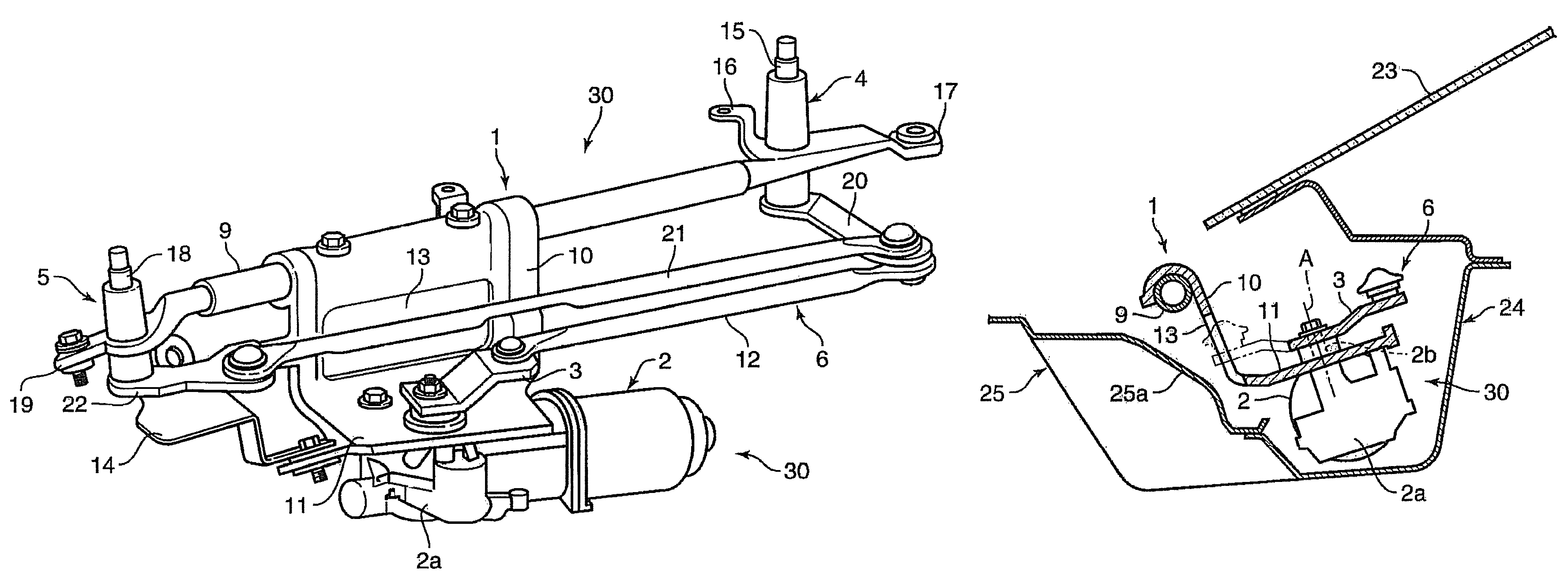
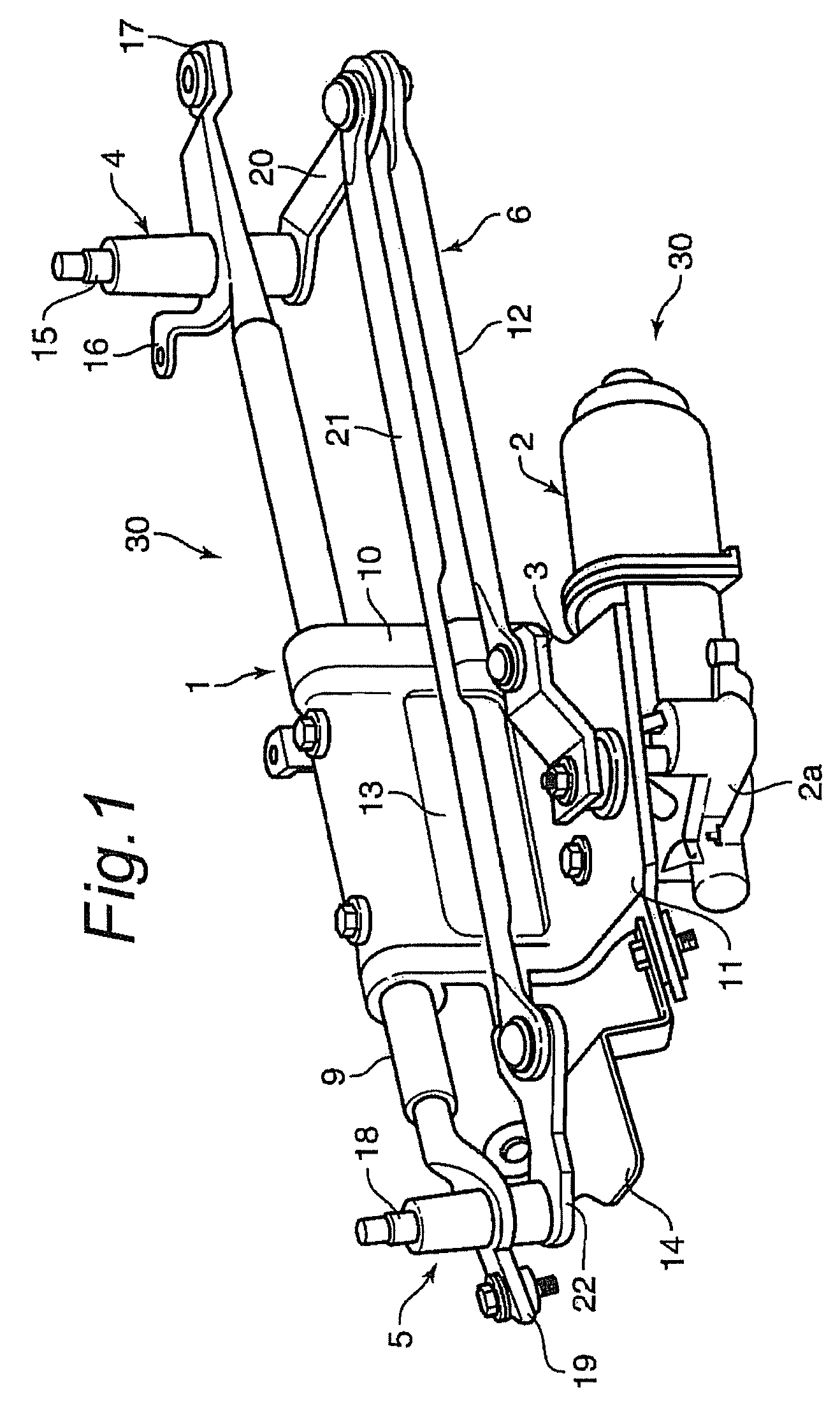
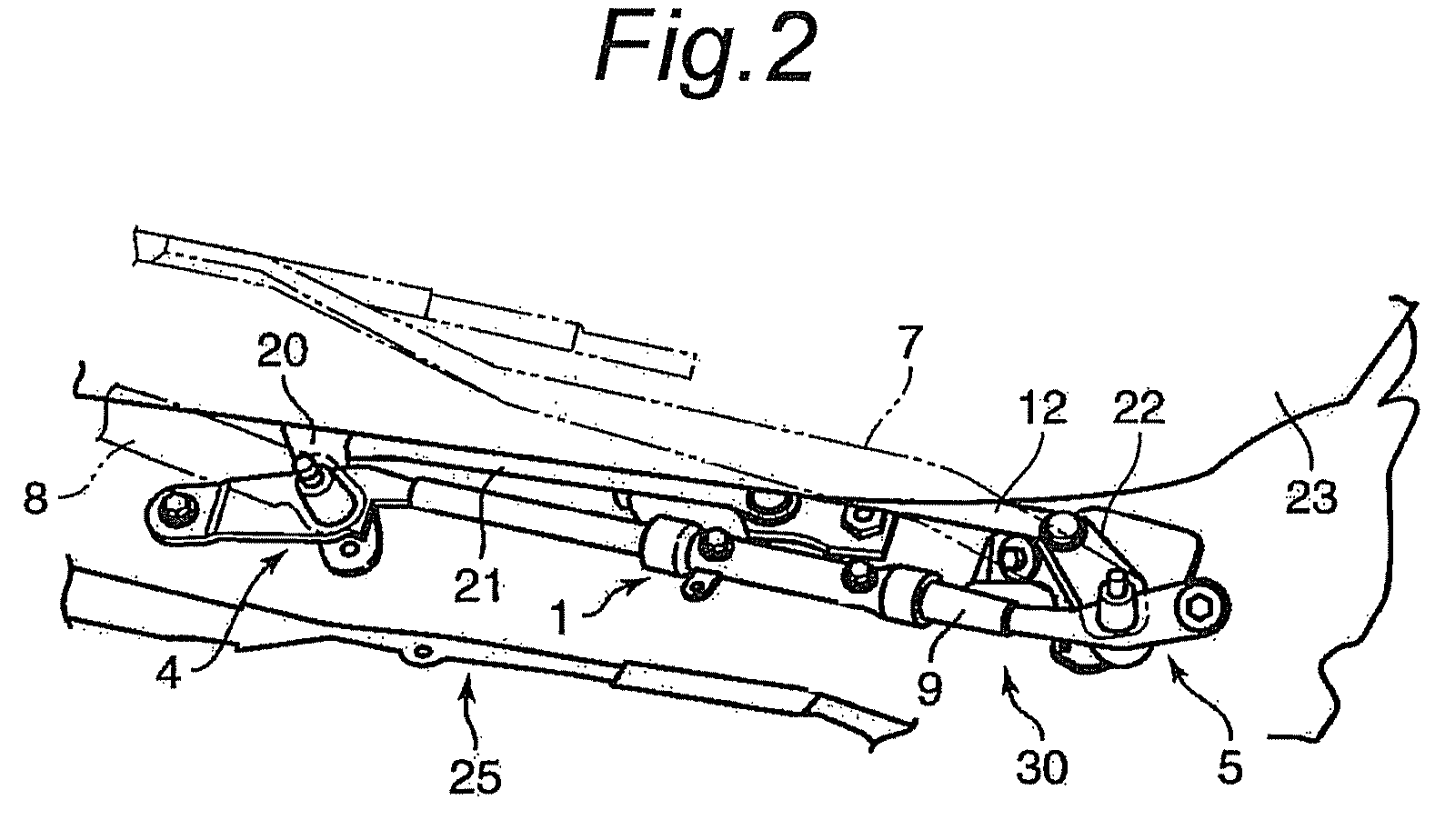
[0017]FIGS. 1 and 3 show a vehicle windshield wiper system embodying the present invention. This wiper system comprises a wiper motor (electric motor) 2 mounted on a support base 1, a crank arm 3 actuated by this wiper motor 2, a link mechanism 6 that transmits the actuating force of the crank arm 3 to a pair of pivot units 4 and 5 mounted on the support base 1 and a pair of wiper arms 7 and 8 having base ends thereof pivotally supported by the corresponding pivot units 4 and 5.

[0018]The support base 1 comprises a connecting rod 9 that extends laterally across the width of the vehicle body, and have two lateral ends that are fixedly attached to a vehicle body as will be described hereinafter. The two pivot units 4 and 5 are fixedly mounted on corresponding lateral end portions of the connecting rod 9. The connecting rod 9 may also consist of any member other than a rod that is laterally elongated, and provided with a required mechanical strength.

[0019]The support base 1 further comp...


PUM


Abstract

In a vehicle windshield wiper system, a support base includes a connecting rod (9) fixedly attached to a vehicle body and extending across a width of the vehicle body, and a base member (10, 11) depending from an intermediate part of the connecting member. A wiper motor (2) attached to a lower surface of a horizontal wall portion (11) of the base member, and a crank arm (3) is attached to an output shaft of the wiper motor. The base member is formed with an opening (13) to avoid an interference with the crank arm as the crank arm undergoes the rotative movement. The opening in the support base prevents an interference with the movement of the crank arm, and this allows the crank arm and an associated link mechanism (6) to be placed opposite to a vertically intermediate part of the support base, and immediately adjacent to the support base. Therefore, the windshield wiper system can be accommodated in a readily available space (24) under the lower edge of the windshield.

Description

TECHNICAL FIELD[0001]The present invention relates to a vehicle windshield wiper system comprising a wiper motor, a crank arm actuated by the wiper motor and a link mechanism for transmitting the actuating force applied to the crank arm to a left and right pivot assembly that support corresponding wiper arms.BACKGROUND OF THE INVENTION[0002]Japanese patent laid open publication (kokai) No. 2006-315511 discloses a vehicle windshield wiper system comprising a wiper motor, a crank arm actuated by the wiper motor and a link mechanism for transmitting the actuating force applied to the crank arm to a left and right pivot assembly that support corresponding wiper arms 7 and 8. The entire wiper system is received in a recess defined under and along the lower edge of the windshield, and the wiper motor is placed under a plate member to keep off water from the wiper motor so that the rusting and corrosion of the wiper motor and pivot shafts may be avoided.[0003]In this previously proposed wi...

Claims


Application Information

Patent Timeline
Patent Type & Authority Patents(United States)
IPC IPC(8): B60S1/06B60S1/24
CPCB60S1/0427B60S1/24
Inventor IGARASHI, YUJISEKIGUCHI, KAZUHIROKATO, MIKITOKISHIMOTO, JUNJI
Owner MITSUBA CORP
Learn More