NMR-MAS probehead with integral transport conduit for an MAS-rotor

a technology of mas-rotor and probe head, which is applied in the direction of measuring leads/probes, geological measurements, and reradiation, etc., can solve the problems of increasing instrumental expense, requiring a large amount of force for removal of probe head or reinsertion of probe head into magnet, and complex overall procedure, so as to facilitate temperature control or cooling, improve or facilitate electromagnetic shielding, and eliminate undesired heat conducting bridges

Active Publication Date: 2012-07-03
BRUKER BIOSPIN
View PDF15 Cites 11 Cited by
  • Summary
  • Abstract
  • Description
  • Claims
  • Application Information

AI Technical Summary

Benefits of technology

[0016]Only the tube of the probe head projects through the room temperature bore. The side of the room temperature bore of the NMR magnet opposite the probe head does not require a superstructure, which facilitates the construction of an NMR apparatus, in particular of an NMR spectrometer. The overall sample change (rotor change) can be performed only from one side of the NMR magnet, i.e. from the side of the NMR probe head (which is typically the lower side of the NMR magnet) via a pneumatic lifting system. The sample change can thereby be automated. A semi-automatic sample change (with manual change trigger, but automatic change execution after change trigger) is preferably provided.
[0030]The present invention also concerns an NMR apparatus comprising a superconducting magnet arrangement with a room temperature bore into which an inventive probe head is inserted. The NMR probe or the MAS rotor in the probe head containing the sample can be easily changed, in particular, without removing the probe head. The invention facilitates assembly of the NMR apparatus in comparison with prior art. The NMR apparatus is preferably designed as a complete NMR spectrometer.

Problems solved by technology

Removal of the probe head or also reinsertion of the probe head into the magnet may require a considerable amount of force due to eddy currents induced in the metal parts of the probe head, in particular in the shielding tube, and the net weight of the probe head.
A rotor change, i.a. new positioning of the probe head in the magnet, requires in most cases renewed shimming such that this overall procedure is very complex.
Due to the fact that the transport conduit is guided through the room temperature bore, the room temperature bore is obstructed, in particular, also above the magnet, thereby increasing the instrumental expense.

Method used


Image

  • NMR-MAS probehead with integral transport conduit for an MAS-rotor
  • NMR-MAS probehead with integral transport conduit for an MAS-rotor
  • NMR-MAS probehead with integral transport conduit for an MAS-rotor

Examples


Embodiment Construction

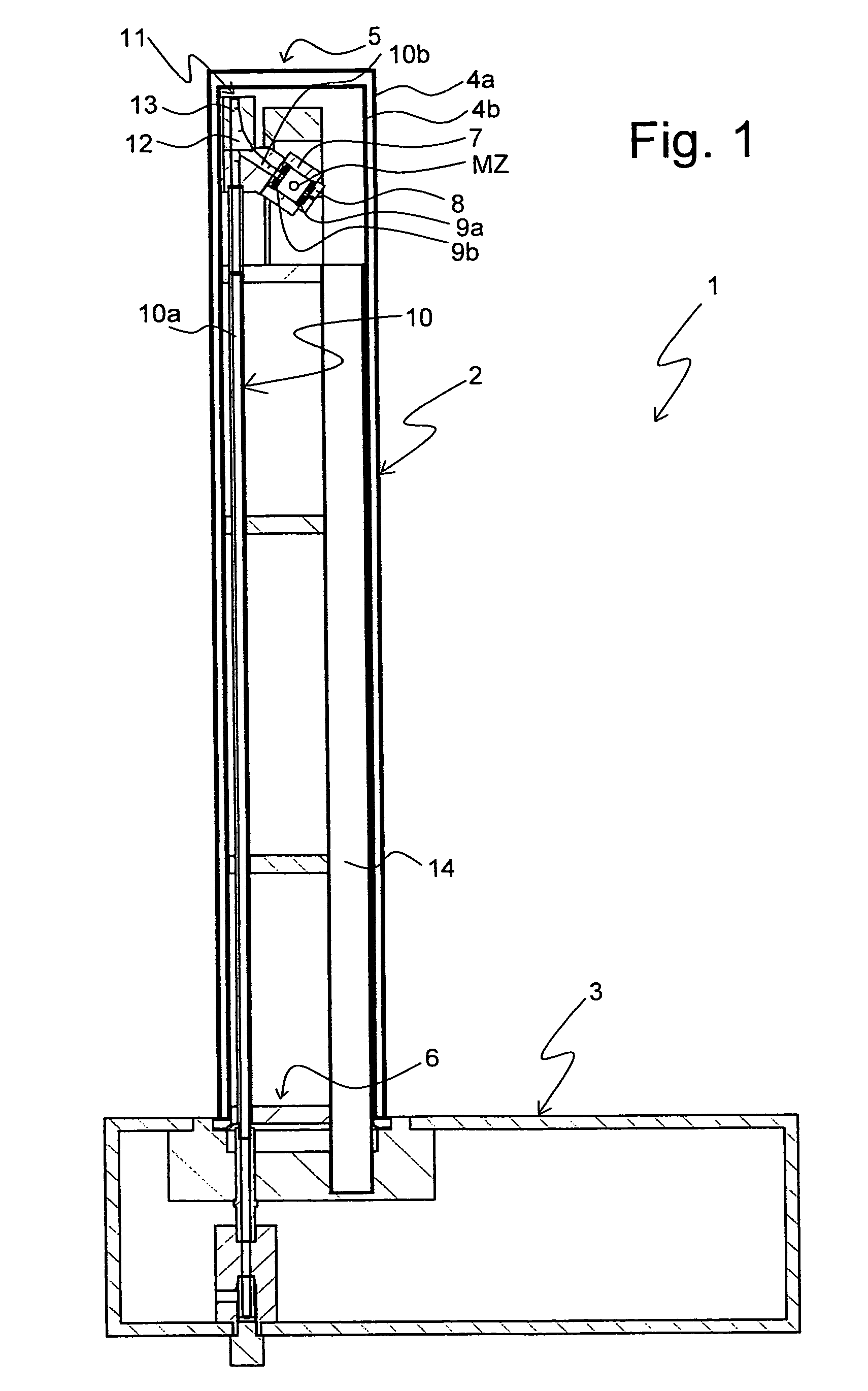
[0043]The invention concerns a new system for changing MAS rotors in an MAS-NMR probe head, wherein the probe head remains mounted in the magnet of an NMR spectrometer.

[0044]FIG. 1 shows an inventive NMR-MAS probe head 1 in a vertical cross-sectional plane. The probe head 1 substantially comprises a tube 2 to be inserted into the room temperature bore of a magnet for an NMR measurement, and a bottom box 3. The tube 2 is mounted to the bottom box 3. The tube 2 projects past the bottom box 3 (in the present case) in a vertical direction. The bottom box 3 remains outside of the room temperature bore of the magnet. The overall probe head 1 is typically held or mounted, in particular, to the magnet or a substructure of the magnet, via the bottom box 3.

[0045]The tube 2 has a double wall (comprising an outer wall 4a and an inner wall 4b) with a vacuum in between such that the tube 2 is simultaneously formed as a Dewar vessel for thermal insulation from the surroundings (usually at room tem...


PUM


Abstract

A nuclear magnetic resonance (NMR) magic angle spinning (MAS) probe head (1; 61) for measuring a measuring substance in an MAS rotor (21a-21c), comprises a bottom box (3) and a tube (2) mounted to the bottom box (3) and projecting from the bottom box, wherein, in the area of the end (5) of the tube (2) facing away from the bottom box (3), an MAS stator (7; 62) is disposed within the tube (2) for receiving an MAS rotor (21a-21c), and with a pneumatic sample changing system for supplying and discharging an MAS rotor (21a-21c) to / from the MAS stator (7; 62). A transport conduit (10) is provided for pneumatically transferring an MAS rotor (21a-21c) within the transport conduit (10), wherein the transport conduit (10) extends in the inside of the tube (2) from the bottom box (3) to the MAS stator (7; 62). The probe head realizes fast change between different MAS rotors and facilitates RF shielding and keeping of defined extreme temperature conditions.

Description

[0001]This application claims Paris Convention priority of DE 10 2008 054 152.4 filed Oct. 31, 2008 the complete disclosure of which is hereby incorporated by reference.BACKGROUND OF THE INVENTION[0002]The invention concerns a nuclear magnetic resonance (NMR) magic angle spinning (MAS) probe head for measuring a measuring substance in an MAS rotor, with a bottom box and a tube that is mounted to the bottom box and projects therefrom, wherein an MAS stator is disposed within the tube in the area of the end of the tube facing away from the bottom box for receiving an MAS rotor, and with a pneumatic sample changing system for supplying and removing an MAS rotor to / from the MAS stator.[0003]An NMR-MAS probe head of this type is disclosed e.g. in the technical poster “Development of a CryoMAS™ HR-MAS-MAG NMR Probe for High-field WB Magnets”, Sid Shevgoor et al., Doty Scientific, Columbia, S.C., USA presented at ENC 2005, Providence, R.I., USA, accessible on the internet on Oct. 9, 2008 a...

Claims


Application Information

Patent Timeline
Patent Type & Authority Patents(United States)
IPC IPC(8): G01V3/00
CPCG01R33/307G01R33/31G01R33/34G01R33/3403G01R33/30
Inventor ARMBRUSTER, MARTINKNOTT, BENNO
Owner BRUKER BIOSPIN
Why Eureka
Try Eureka