Rock drilling method and rock drilling machine

a drilling method and rock technology, applied in the field of pulse drilling machines, can solve problems such as system failure, and achieve the effect of improving the drilling efficiency and accuracy of the drilling method

Inactive Publication Date: 2012-07-10
ATLAS COPCO ROCK DRILLS
View PDF28 Cites 1 Cited by
  • Summary
  • Abstract
  • Description
  • Claims
  • Application Information

AI Technical Summary

Benefits of technology

[0007]Through the invention is provided a possibility of damping rock reflexes occurring during drilling, whereby a number of important advantages are achieved, such as possibility of drilling with an increased rock drilling efficiency. It is also achieved that the machine can be protected against the strain which occurs from reflected shock waves, which is expected to result in longer working life of a machine constructed according to the invention.
[0008]In a previously known impact drilling machine including an impact piston, the purpose of the so called damping piston is to transfer the feed force against the rock from the machine housing to the drill bushing further over the adapter, over the drill string to the drill bit for its contact against the rock. According to the background art, the damping piston is prestressed through a hydraulic / pneumatic spring, being comprised of a hydraulic fluid in a chamber which often is in connection with a hydraulic / pneumatic accumulator.
[0009]If the shock wave generated by the impact piston through the drill string is not matched to the rock impedance, reflexes are returned through the drill string. If the rock is hard compared to the shock wave force, mainly compressive reflexes are obtained, the amplitudes of which can be twice as great as that of the incident shock wave.
[0010]The pressure reflexes force the drill bushing and the damping piston in the direction from the drill string, whereby hydraulic oil is loaded into the accumulator. The pressure therein thereby pushes back the damping piston and the drill bushing to the initial position against a mechanical strop in machine housing. The flexibility of a connected accumulator provides a resilient function which protects the drilling machine against high strains and vibrations. This increases the working life of the drilling machine and allows greater power to be transferred.
[0011]In percussive piston devices there are thus used separate components in order to obtain the damping functions. This systems, however, have proved to operate badly during drilling with high frequencies (>200 Hz).
[0012]Through the present invention it's obtained that the impulse piston itself of a pulse drilling machine is used to provide a damping function. Hereby the need of separate components such as particular damping pistons is avoided. The advantages are on the one hand the possibility of obtaining a very rapid damping system, on the other hand reducing the number of moveable parts and components, which results in better economy.
[0013]By the fluid flow channel being connected to a pressure fluid accumulator, there are achieved enhanced possibility of damping fast processes.
[0014]By the first fluid chamber being a separate damping chamber which is arranged radially outside the impulse piston it is achieved that the damping piston and the associated hydraulic system can be dimension respectively be controlled in consideration only of the damping function without taking into account possible other functions.
[0015]By the fluid flow channel including a restriction, and in particular a throttling slot between the housing and the impulse piston, it is achieved that the energy being reflected is absorbed in an advantageous way.
[0016]By a supply channel for fluid being connected to the damping chamber for providing a leak flow, there is allowed a provision for cooling damped energy in the machine and thereby enhanced operating properties.
[0018]By means for sensing the pressure in the first fluid chamber being arranged, the possibility is allowed to utilize signals in respect of sensed pressure, for drilling control.
[0019]By said means for abrupt change of fluid pressure affecting an impulse piston being controllable starting out from sensed pressure in the first fluid chamber, it is possible to control means for generating the shock wave pulses. This in particular in order to regulate the frequency of generation of shock wave pulses. This in order to regulate in the direction of reduction of the shock wave reflexes.
[0021]It is particularly advantageous to control the length of the shock wave pulse as a response to sensed shock wave reflex. This way the invention can be used in order such that the drilling parameters are adjusted in real time, to for example fluctuating hardness in rock to be drilled, in a manageable way.
[0022]Advantages of a device according to the invention corresponding to the above advantages in respect of the different device aspects are obtained in respect of corresponding method claims. Further features and advantages of the invention and its different aspects will be clear from the following detailed description.

Problems solved by technology

This systems, however, have proved to operate badly during drilling with high frequencies (>200 Hz).

Method used


Image

  • Rock drilling method and rock drilling machine
  • Rock drilling method and rock drilling machine
  • Rock drilling method and rock drilling machine

Examples


Embodiment Construction

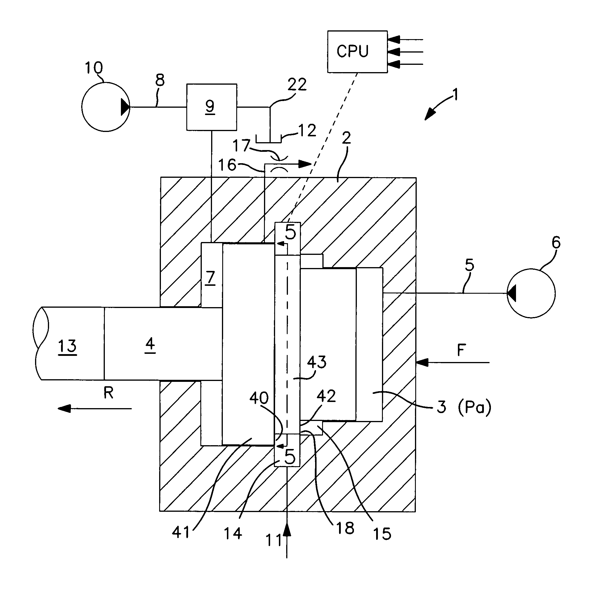
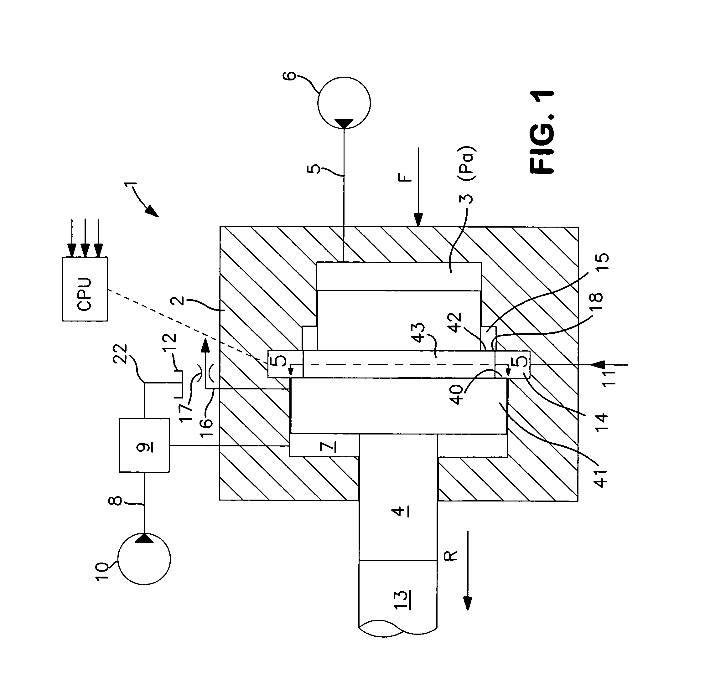
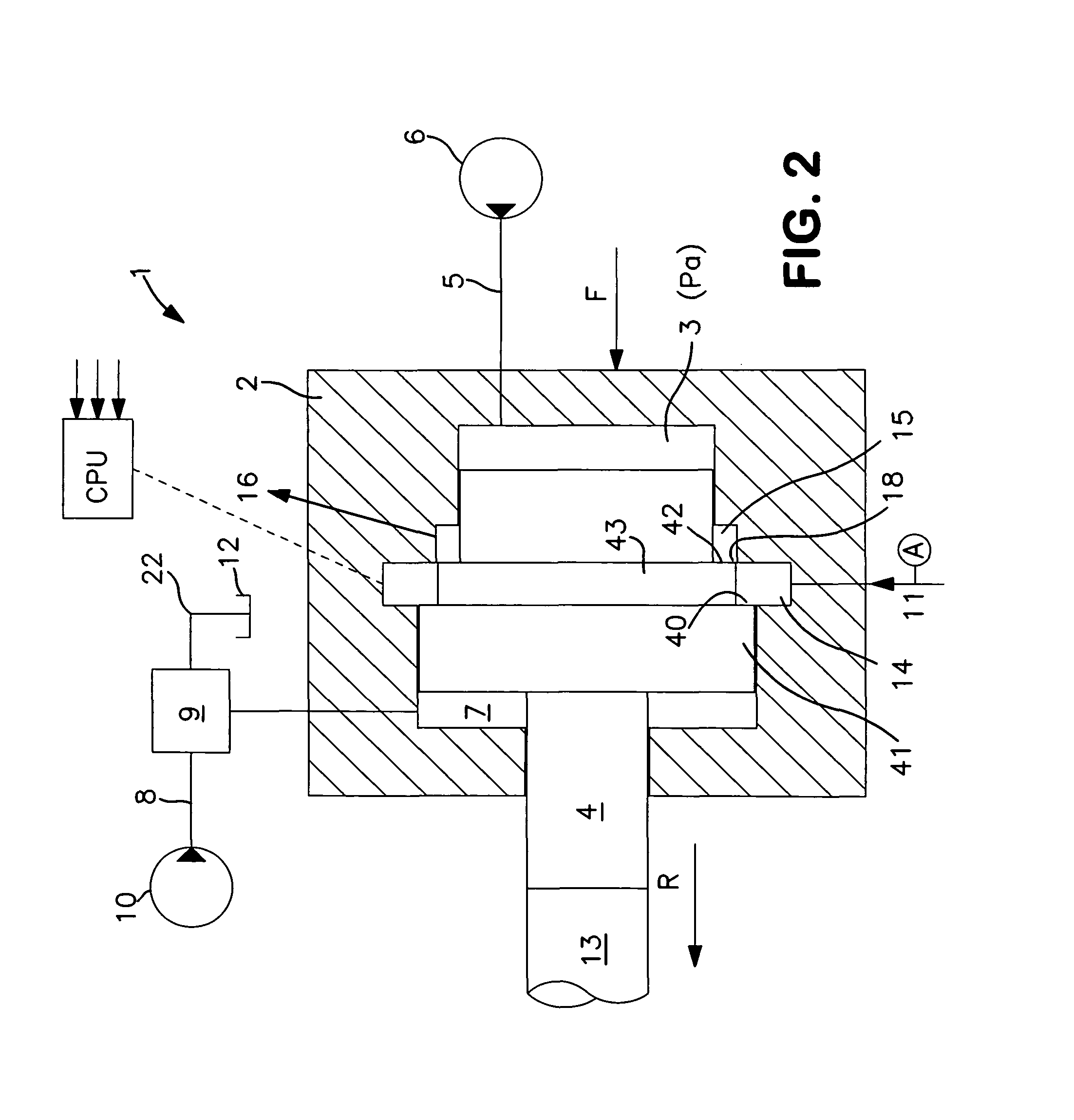
[0029]With reference to FIG. 1 a pulse generator of a pulse drilling machine according to the invention is generally indicated with 1. In a housing 2 an impulse piston 4 is restrictedly moveable to and fro. The impulse piston contacts at a partition section against an upper portion, indicated with 13, of a drill string. Adjoining to the underside of the inside impulse piston 4 is arranged a counter force chamber 7 which is pressurised with counter pressure Pm for action with a counter force on the impulse piston in a direction opposite to a tool direction R.

[0030]The pressure in the chamber 7 is controlled in that a valve 9 periodically transmits an initial pressure from a pump 10 over a pressure conduit 8 to this chamber 7. From that valve also leads a tank conduit 18 to tank 12 for periodic relieve of the first fluid chamber 7.

[0031]Adjoining to the other side of the impulse piston 4 is arranged a pressurizing chamber 3 which is capable of being pressurized with pressure Pa for ge...


PUM

PropertyMeasurementUnit
frequenciesaaaaaaaaaa
forceaaaaaaaaaa
pressureaaaaaaaaaa

Abstract

A pulse drilling machine (1;1′) for the generating of shock wave pulses in a tool direction (R) has an impulse piston (4;4′) with a housing (2), and a device (8) for abruptly changing fluid pressure influencing the impulse piston to achieve a force resultant on the impulse piston in the tool direction to generate a shock wave pulse in a drill string (13; 13′) which is connected to the machine, a first fluid chamber (14;3′) inside the housing which in operation is arranged to exert a pressure in the tool direction on the impulse piston. The machine has a fluid flow channel (11; 18; 19), which includes a device for damping fluid flow flowing from the first fluid chamber through the fluid flow channel obtained when influencing the impulse piston (4; 4′) in a direction opposite to the tool direction (R) by rock reflexes in the drill string during drilling.

Description

FIELD OF THE INVENTION[0001]The invention concerns a pulse drilling machine for the generating of shock wave pulses. The invention also concerns a method for generating shock wave pulses. Further, the invention concerns a drilling rig.BACKGROUND OF THE INVENTION[0002]During rock drilling, shock wave pulses are generated in the form of pressure force pulses which are transferred from a shock wave producing device such as an impulse device through a drill string to a drill bit. Drill bit insert buttons are thereby pressed against the rock with high intensity and achieves crushing and forming of crevices in the meeting rock.[0003]In conventional rock drilling machines, the shock wave pulses are generated by means of an impact piston, which strikes against a drill shank for the further transfer of the shock wave to the drill string.[0004]The present invention, however, concerns another type of shock wave generating rock drilling machines, herein called pulse drilling machines. These mac...

Claims


Application Information

Patent Timeline
Patent Type & Authority Patents(United States)
IPC IPC(8): E21B1/28
CPCB25D9/125B25D9/145E21B7/24E21B1/02B25D17/245B25D9/14E21B44/00E21B1/36
Inventor TUOMAS, GORAN
Owner ATLAS COPCO ROCK DRILLS
Why Eureka
Try Eureka