
MEMS vascular sensor

a vascular sensor and sensor technology, applied in the field of vascular sensors, can solve the problems of wall shear stress, in particular near-wall shear stress, remains an engineering challenge, particle image velocity velocimeter, and may have an increased noise level

Inactive Publication Date: 2012-07-10
UNIV OF SOUTHERN CALIFORNIA
View PDF15 Cites 14 Cited by
  • Summary
  • Abstract
  • Description
  • Claims
  • Application Information

AI Technical Summary

Benefits of technology

The patent describes a micromachined sensor for measuring fluid shear stress and a method of fabricating it. The sensor includes a cavity etched in a substrate and a heat sensing element disposed on the front-side surface of the substrate. The sensor is connected to an electronic system on the backside surface of the substrate. The sensor measures changes in heat convection from the sensing element to the surrounding fluid when it is heated, which can be used to calculate the shear stress of the fluid. The sensor can be attached to a flexible catheter for measuring shear stress in blood vessels. The technical effects of the patent include the development of a reliable and accurate method for measuring fluid shear stress, which can help in the diagnosis and treatment of vascular diseases.

Problems solved by technology

Measurement of wall shear stress, in particular near-wall shear stress, remains an engineering challenge, however.
The wall shear stress as obtained from a laser Doppler velocimeter or a particle image velocimeter, may have an increased noise level, due to the reflection from the wall.
Another challenge is the application of in-situ devices such as heated wires, which have to be employed close to the vessel wall to measure shear stress.
This causes a decrease in the sensitivity of the measurements.
Measuring temporal and spatial variations in shear stress, both of which have been implicated in the pathogenesis of atherosclerosis, is especially challenging.
Operating the MEMS sensors in a liquid environment, as may be necessary in many biomedical applications, may affect the sensitivity of the MEMS sensors.
For example, MEMS sensors that are driven by front-side wire bonding may require insulation using sealants, which however may undergo expansion after prolonged exposure to the fluidic environment.
Also, in MEMS sensors for which wire bonding is established on the front side, the elevation of microcircuitry on the same side of sensing element may disturb the local flow milieu, thus negatively affecting the precision of the shear stress measurement.

Method used


Image

  • MEMS vascular sensor
  • MEMS vascular sensor
  • MEMS vascular sensor

Examples


Embodiment Construction

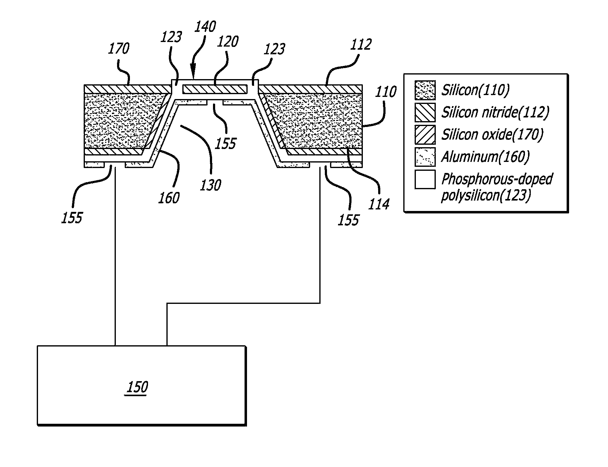
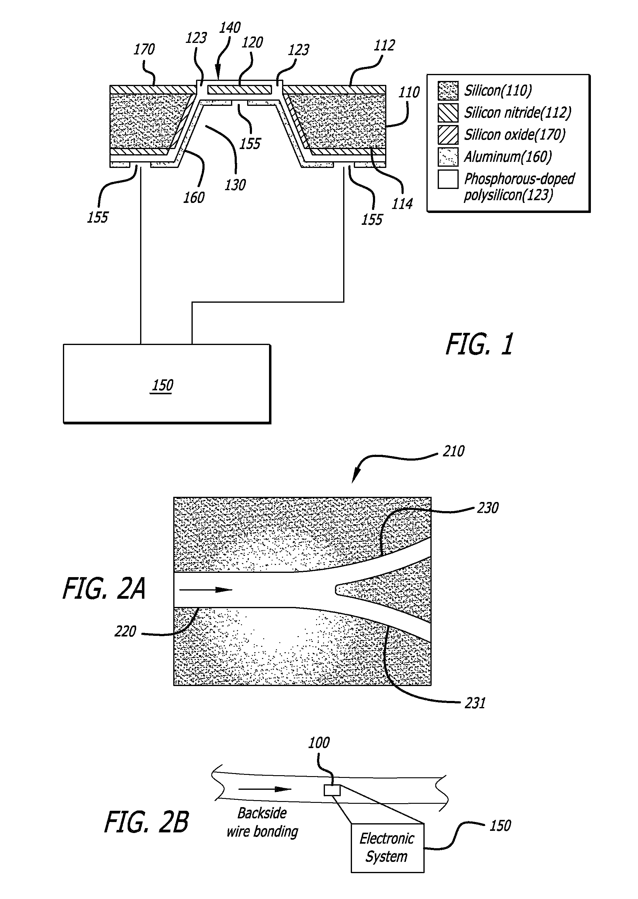
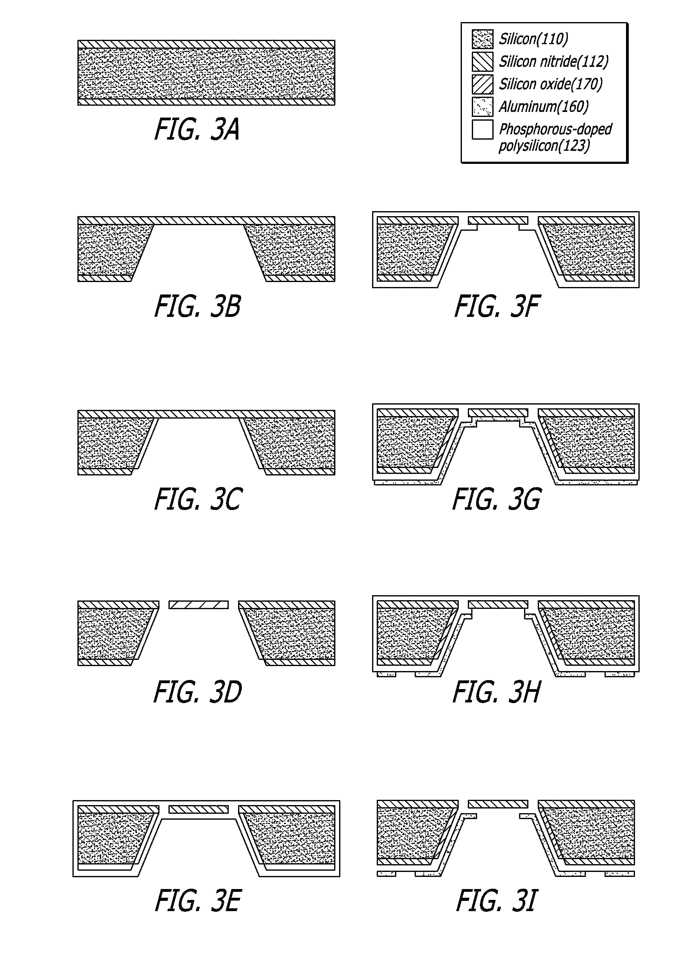
[0026]A system and method are disclosed for measuring fluid shear stress with a MEMS shear stress sensor, and for fabricating the MEMS sensor. The MEMS sensor may be backside wire bonded, and may operate based on basic heat transfer principles. The backside wire bonding may insulate the micro-circuitry in the MEMS sensor from the fluid. The MEMS sensor may include an etched cavity that may improve the sensitivity of the sensor by minimizing heat conductance loss from the heat sensing component of the sensor.

[0027]FIG. 1 is an overall schematic diagram of a MEMS shear stress sensor 100, constructed in accordance with one embodiment of the methods and systems described in this disclosure. In overview, the MEMS sensor 100 may include: a substrate 110 having a front-side surface 112 and a backside surface 114 opposite the front-side surface; a diaphragm 120 overlying a cavity 130 etched within the substrate 110; a heat sensing element 140 disposed on the front-side 112 of the substrate ...


PUM

PropertyMeasurementUnit
temperatureaaaaaaaaaa
sizeaaaaaaaaaa
depthaaaaaaaaaa

Abstract

A micromachined sensor for measuring vascular parameters, such as fluid shear stress, includes a substrate having a front-side surface, and a backside surface opposite the front-side surface. The sensor includes a diaphragm overlying a cavity etched within the substrate, and a heat sensing element disposed on the front-side surface of the substrate and on top of the cavity and the diaphragm. The heat sensing element is electrically couplable to electrode leads formed on the backside surface of the substrate. The sensor includes an electronic system connected to the backside surface and configured to measure a change in heat convection from the sensing element to surrounding fluid when the sensing element is heated by applying an electric current thereto, and further configured to derive from the change in heat convection vascular parameters such as the shear stress of fluid flowing past the sensing element.

Description

CROSS REFERENCE TO RELATED APPLICATIONS[0001]This application is a divisional application of U.S. patent application Ser. No. 11 / 196,849, filed Aug. 4, 2005, entitled “MEMS Vascular Sensor,” now U.S. Pat. No. 7,367,237 B2, issued May 6, 2008, which claims the benefit of priority under 35 U.S.C. §119(e) from co-pending, commonly owned U.S. provisional patent application Ser. No. 60 / 601,101, filed on Aug. 12, 2004, entitled “Backside Wire Bonding For Micro Circuitry.” The entire content of both of these applications is incorporated herein by reference.GOVERNMENT'S INTEREST IN APPLICATION[0002]This invention was made with government support under Grant No. HL068689-01, awarded by the National Institutes for Health. The government has certain rights in the invention.BACKGROUND[0003]Coronary artery disease may be one of the leading causes of morbidity and mortality in the industrialized nations. Vascular parameters, in particular shear stress acting on blood vessel walls, may play an imp...

Claims


Application Information

Patent Timeline
Patent Type & Authority Patents(United States)
IPC IPC(8): C23C14/34
CPCB81C1/00246G01N3/24
Inventor HSIAI, TZUNG K.SOUNDARARAJAN, GOPIKRISHNANKIM, EUN SOKYU, HONGYUROUHANIZADEH, MAHSALIN, CHRISTINA TIANTIAN
Owner UNIV OF SOUTHERN CALIFORNIA
Learn More