Multilayer thermal barrier coating

a thermal barrier coating and multi-layer technology, applied in the direction of superimposed coating process, machine/engine, natural mineral layered products, etc., can solve the problem of increasing residual stresses in the tbc, destabilizing the tbc layer and its spallation, and the mitigation mechanism cannot efficiently rely on proposed solutions, etc. problem, to achieve the effect of improving thermal barrier coating, thermal barrier coating, and improving resistan

Inactive Publication Date: 2012-07-10
ANSALDO ENERGIA IP UK LTD +1
View PDF7 Cites 13 Cited by
  • Summary
  • Abstract
  • Description
  • Claims
  • Application Information

AI Technical Summary

Benefits of technology

[0021]The CMAS attack mechanism has been identified to proceed through Ca diffusion in the YSZ leading to its destabilization even through solid-state reaction. The TBC degradation mechanism does not need to involve a molten deposit, as always assumed up to now; it can happen through gaseous contaminants reacting directly with YSZ leading to Ca-infiltration in the YSZ. The diffusion of Ca in the YSZ layer changes the microstructure of the as-deposited, partially stabilized zirconia with 6-8 wt % yttria leading to an increased content of fully stabilized zirconia. This increased content of fully stabilized zirconia leads to an increase of residual stresses in the TBC and the destabilization of the TBC layer and its spallation.
[0027]Under the expression “protective layer” a true essentially contiguous / continuous layer structure is to be understood, protecting / covering an essential part, if not all of the surface exposed to the hot gas pathway, and which protective layer prevents CMAS-attack. Preferably, therefore, the protective layer forms a contiguous layer covering all of the chemically stabilized zirconia layer on the component.

Problems solved by technology

This increased content of fully stabilized zirconia leads to an increase of residual stresses in the TBC and the destabilization of the TBC layer and its spallation.
Therefore, the mitigation mechanism cannot efficiently rely on proposed solutions according to the state-of-the-art of impermeable or sacrificial coatings protecting from molten deposit contamination.
As already mentioned above, indeed it is even sometimes sufficient if there is provided such an infiltration zone without an actual protective layer, as long as this infiltration zone essentially covers the topmost surface structure of the thermal barrier coating lying underneath, protecting it from the contaminant substances.
Such a high sulphur content is never achieved under normal operating conditions in a gas turbine.

Method used


Image

  • Multilayer thermal barrier coating
  • Multilayer thermal barrier coating
  • Multilayer thermal barrier coating

Examples


Embodiment Construction

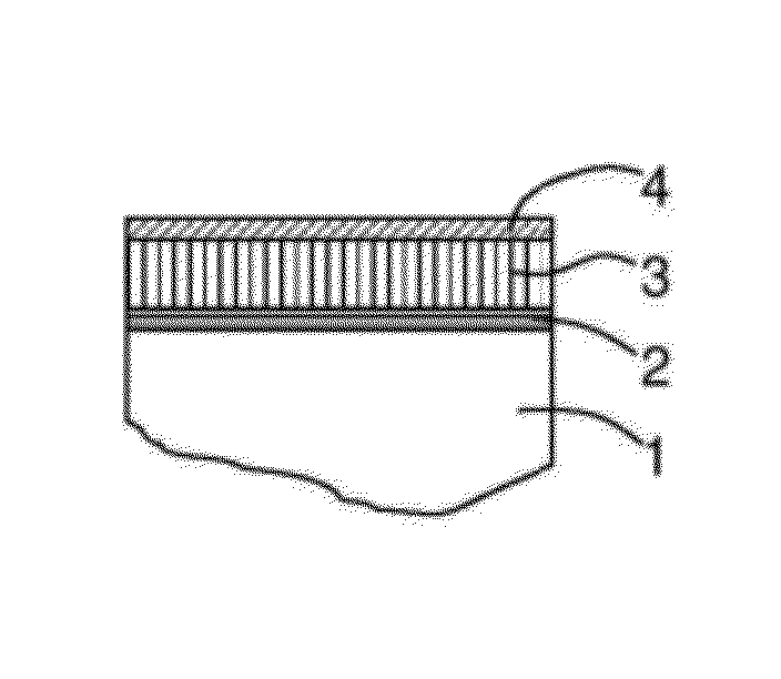
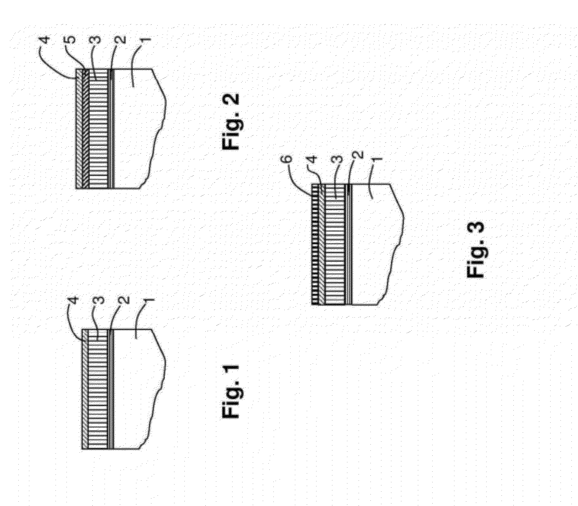
[0048]Referring to the drawings, which are for the purpose of illustrating the present preferred embodiments of the invention and not for the purpose of limiting the same, FIG. 1 shows a partial area cut through a possible component structure.

[0049]The structure includes base metal of the component 1. On this base metal normally there is provided a bond coat layer 2 for adhesively attaching the subsequent ceramic thermal barrier coating layer 3 made of YSZ or analogous systems. According to exemplary embodiments of the invention, as a top layer there is provided a calcium sulfate layer 4 as a protective layer.

[0050]It is to be noted that the thermal barrier coating layer 3 may be a structure having several individual identical or different material layers of barrier coating material.

[0051]As indicated schematically in FIG. 2, normally, in particular when using liquid infiltration or dip coating for applying the protective layer 4, an infiltration zone 5 is formed, which is a region ...


PUM

PropertyMeasurementUnit
thicknessaaaaaaaaaa
thickaaaaaaaaaa
temperatureaaaaaaaaaa

Abstract

Components (1) have a thermal barrier coating (2-6) on the surface thereof, wherein the thermal barrier coating includes at least one layer (3) having chemically stabilized zirconia, and wherein at least indirectly adjacent to the layer (3) with chemically stabilized zirconia and on its surface facing side, there is provided a protective layer (4) and / or a infiltration zone (5) which does not react with environmental contaminant compositions that contain oxides of calcium and which does not react with the material of the layer (3) having chemically stabilized zirconia. Methods for making such components as well as to uses of specific systems for coating thermal barrier coatings, can prevent CMAS.

Description

[0001]This application claims priority under 35 U.S.C. §119 to European patent application no. 08104164.2, filed 29 May 2008, the entirety of which is incorporated by reference herein.BACKGROUND[0002]1. Field of Endeavor[0003]The present invention relates to the field of yttria-based thermal barrier coatings and their protection from calcia-alumina-magnesia silicate (CMAS) attack.[0004]2. Brief Description of the Related Art[0005]A thermal barrier coating (TBC) can be destabilized by environmental contaminants, mostly by calcia-alumina-magnesia silicates (Ca—Mg—Al—SiO, also called CMAS; note that S stands for SiO and not for sulfur) forming a deposit that can react with yttria-stabilized zirconia and lead to the TBC spallation. For a general description of the corresponding mechanisms as perceived in the state-of-the-art, reference is for example made to the introductory portion of U.S. Pat. No. 5,660,885. In recent years several solutions have been proposed in this respect.[0006]U....

Claims


Application Information

Patent Timeline
Patent Type & Authority Patents(United States)
IPC IPC(8): B32B18/00B32B15/04C23C4/10
CPCC23C4/10C23C28/042C23C28/048F01D5/28F01D5/288Y02T50/67Y10T428/12479F05D2230/90F05D2300/611Y10T428/12667Y10T428/12806Y10T428/12535Y02T50/672Y02T50/60
Inventor WITZ, GREGOIRE ETIENNEBOSSMANN, HANS-PETERSHKLOVER, VALERYBACHEGOWDA, SHARATH
Owner ANSALDO ENERGIA IP UK LTD
Why Eureka
Try Eureka