Composite structure and method for producing a composite structure

a composite structure and composite technology, applied in the field of composite structure and composite structure production, can solve the problems of air pockets, difficult or impossible to remove, and ensure the complete distribution of polymer in the entire mould cavity, so as to reduce load or force, reduce load, and increase the effect of area

Active Publication Date: 2012-07-17
LM GLASSFIBER
View PDF10 Cites 10 Cited by
  • Summary
  • Abstract
  • Description
  • Claims
  • Application Information

AI Technical Summary

Benefits of technology

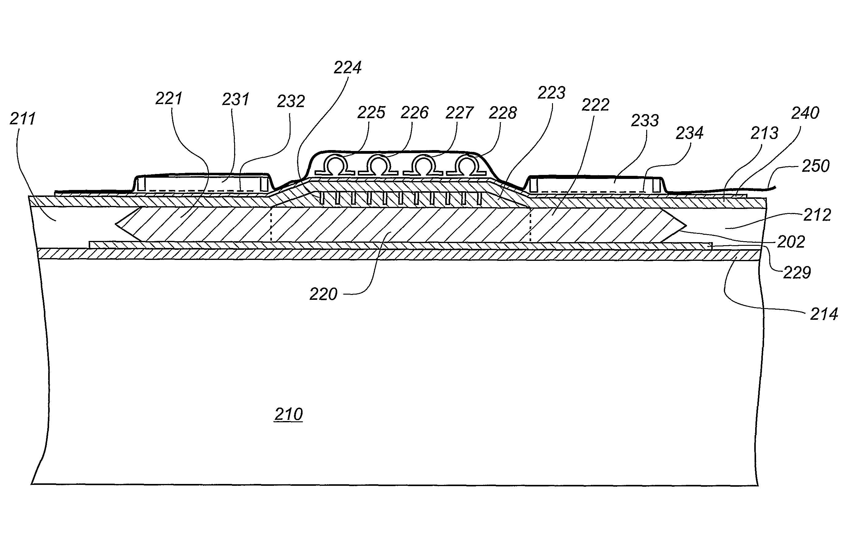
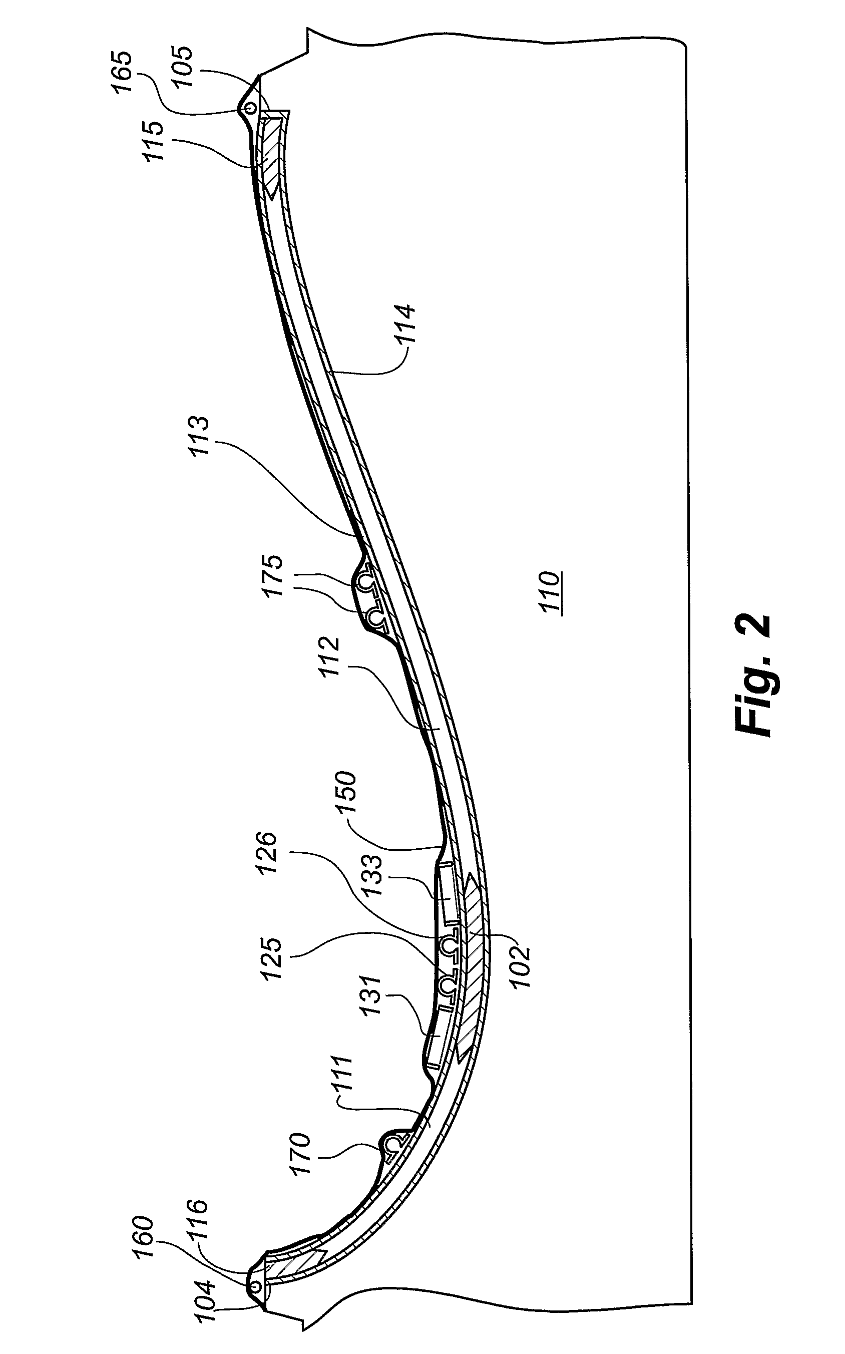
[0021]The terms “distribution medium” or “distribution layer” are to be understood as a layer, which allows a higher flow speed for liquid polymer than the fibre insertion does. The resin distribution network can be provided by being made of a porous material or at least being highly permeable to liquid resin. The upper distribution medium ensures that the resin is distributed quickly along the fibre insertion above the intermediate zone, thus ensuring that a broad flow front of resin is distributed through the intermediate zone of the fibre insertion during impregnation as well as towards the vacuum outlets.
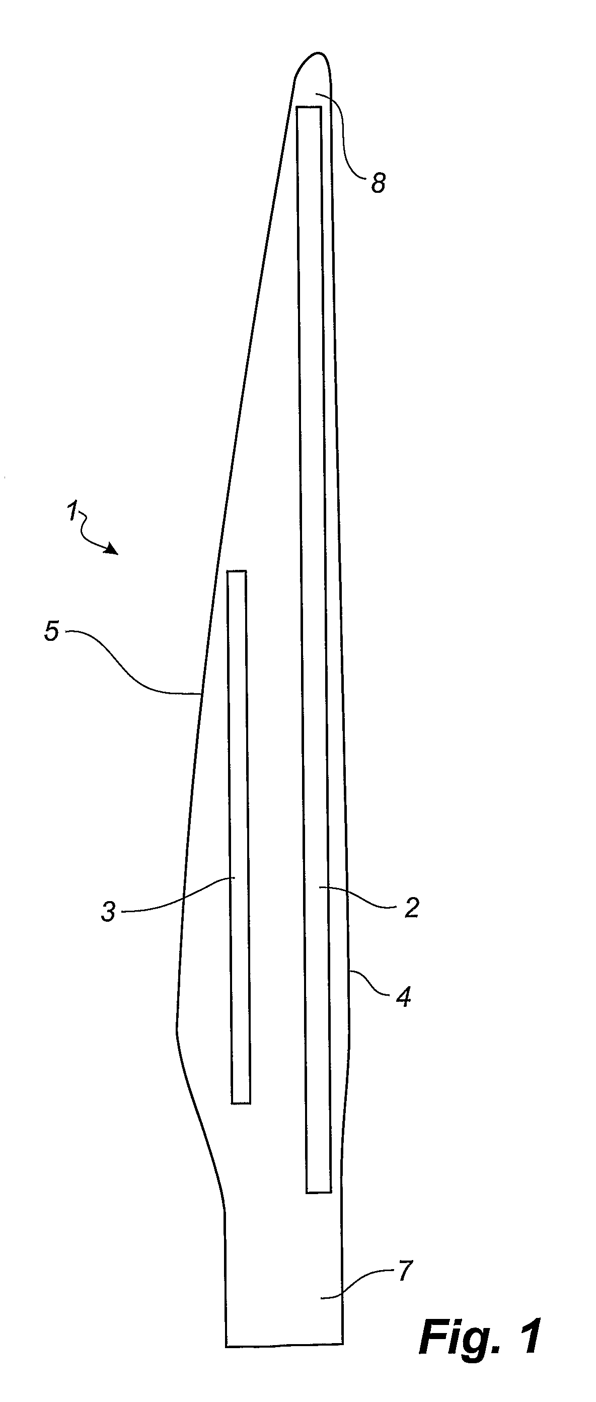
[0022]The combination of the centrally positioned upper distribution layer and the vacuum outlets ensures that the overall time for fully impregnating the fibre insertion is reduced compared to known techniques. Composite structures such as wind turbine blades have over the years become longer and longer and some wind turbine blades are today up to 60 meters or even longer (and blades of a 100 meters or more are contemplated). Therefore, it has become increasingly important to optimise the production of such blades. Even small reductions in the amount of time needed for the different stages of the production of the blades can make the difference on whether for instance three or four working shifts are needed in order to fabricate the blade. Thus, even small reductions of the amount of time needed for each production stage can significantly reduce the necessary man-hours and thereby the overall production cost.
[0024]According to a first embodiment of the method, a lower distribution medium is provided below the fibre insertion, the lower fibre layer at least partially overlapping the first zone and the second zone. The lower distribution medium ensures that the overall impregnation time may be reduced even further and furthermore reduces the probability of formation of air pockets, since the flow fronts are drawn in under the first zone and the second zone. Thus, the flow front of liquid resin first propagates downwards through the intermediate zone of the fibre insertion. When the flow front reaches the lower distribution medium, the flow front is drawn in under the vacuum outlets, and the flow front subsequently moves up through the first zone and the second zone, respectively. In an advantageous embodiment, the lower distribution medium overlaps substantially the entire fibre insertion and can even extend beyond the fibre insertion.
[0026]The plate-like distribution medium, which may become part of the finished composite structure, reduces the load or force with which the resin inlet channels normally influence the fibre laminate, when the vacuum bag presses the inlet channels against the fibre insertion or fibre layers during evacuation and impregnation. The load is reduced since the forces are applied over the bottom surface of the plate-like distribution medium and thus over a much greater area. Hereby, the formation of stress lines or areas is avoided, which during subsequent use of the composite structure could cause a buckling effect. Additionally, it is preferred that the plate-like distribution medium becomes part of the composite structure, since the removal of the distribution medium also could cause the formation of impressions and thus cause areas of reduced strength.
[0031]According to another advantageous embodiment, the plate-like distribution medium comprises a first side and a second side, wherein the distribution medium is tapered towards the first side and / or the second side. Thereby, it is ensured that a gradual transition between different materials having different strengths is obtained, thus minimising the probability of formation of stress lines or areas and thus also reducing the probability of buckling effects for the finished composite structure.
[0052]According to one embodiment, the composite structure additionally comprises a first core material at the first side of the fibre insertion and a second core material at the second side of the fibre insertion. According to another embodiment, the structure additionally comprises one or more fibre layers at a first surface of the composite structure and one or more fibre layers at a second surface of the composite structure. These are of course impregnated with cured resin. The first surface can define the inner surface of for instance a wind turbine shell half part, while the second surface can define the outer surface of the wind turbine shell half part. Alternatively, the outer surface can be defined by a gel coat applied on top of the fibre layer(s). The core material can be provided with channels or grooves filled with cured resin. These resin-filled channels can prevent subsequent delamination of the composite structure.

Problems solved by technology

Ensuring a complete distribution of the polymer in the entire mould cavity is, however, often difficult, and accordingly this often results in so-called dry spots, i.e. areas with fibre material not being sufficiently impregnated with resin.
Thus dry spots are areas where the fibre material is not impregnated, and where there can be air pockets, which are difficult or impossible to remove by controlling the vacuum pressure and possibly an overpressure at the inlet side.
This is a time-consuming and tiresome process.
This is not desirable, especially not when the polymer has not hardened, as it can result in deformations in the inserted fibre material and thus in a local weakening of the structure, which can cause for instance buckling effects.
Furthermore the infusion process has become more complicated, as the impregnation of large shell members, such as blades, requires control of the flow fronts to avoid dry spots, said control may e.g. include a time-related control of inlet channels and vacuum channels.
This increases the time required for drawing in or injecting polymer.
As a result the polymer has to stay liquid for a longer time, normally also resulting in an increase in the curing time.

Method used


Image

  • Composite structure and method for producing a composite structure
  • Composite structure and method for producing a composite structure
  • Composite structure and method for producing a composite structure

Examples


example

[0109]According to a given prototype of a LM61.5 wind turbine blade, the width of the main laminate differs in the longitudinal direction of the blade. The main laminate is approximately 850 mm wide and has a thickness of approx. 42 mm at the widest and thickest part, respectively. The width of the top hat also varies in the longitudinal direction of the blade and is approximately 360-370 mm at the widest part and 150 mm at the slimmest part.

[0110]The core blocks have the following dimensions: w=1-1.2 mm, d=30 mm, h2=2.5+ / −0.5 mm, α=14 degrees, and t=1 mm. The core blocks have varying thickness h, and therefore the height of the first grooves is also varying. The overlap between the first grooves and the second grooves are equal to h2 minus t and is thereby 1.5-2.0 mm.

[0111]The examples have been described according to preferred embodiments. However, the invention is not limited to these embodiments. For example, the width and height of the individual grooves as well as the distance...


PUM

PropertyMeasurementUnit
thickaaaaaaaaaa
thickaaaaaaaaaa
thickaaaaaaaaaa

Abstract

A method for producing a composite structure and a composite structure obtained by the method is described. The method comprises the following steps: a) providing a mold comprising a rigid mold part and a flexible vacuum bag, b) placing a fiber insertion in the mold part, the fiber insertion including a plurality of fiber layers and, when placed in the mold part, having an upper surface and a lower surface as well as a first side and a second side, the fiber insertion including a first zone at the first side and a second zone at the second side, the first zone and the second zone being separated by an intermediate zone, c) placing an upper distribution medium above the intermediate zone of the fiber insertion, the distribution medium comprising a resin distribution network for distributing resin along the upper distribution medium, d) placing a number of resin inlet channels above the upper distribution medium for supplying liquid resin to the resin distribution network, e) placing a first vacuum outlet at least partially overlapping the first zone of the fiber insertion and a second outlet at least partially overlapping the second zone of the fiber insertion, f) placing the vacuum bag on top of the mold part, thus sealing the vacuum bag against the mold part to define a mold cavity, g) evacuating the mold cavity, h) connecting a source of uncured fluid resin to the resin inlet channels so as to feed uncured resin to the resin distribution network in order to fill the mold cavity and to impregnate at least the fiber insertion and the upper distribution medium with uncured resin, and i) allowing the resin to cure in order to form the composite structure.

Description

[0001]This is a U.S. national phase Application filed under 35 U.S.C. 371 of PCT / DK2008 / 000245, filed 27 Jun. 2008 claiming priority benefit from DK Application No. PA 2007 00947, filed 29 Jun. 2007, the entire content of which is hereby incorporated by reference.TECHNICAL FIELD[0002]The present invention relates to a method for producing a composite structure comprising fibre reinforced material by means of vacuum assisted resin transfer moulding, where the fibre reinforced material is impregnated with liquid resin. Furthermore, the invention relates to a composite structure obtained by the method.BACKGROUND[0003]Thus the invention relates to a method for producing fibre composite structures and composite structures obtained by means of VARTM (vacuum assisted resin transfer moulding), where liquid polymer, also called resin, is filled into a mould cavity, in which fibre material priorly has been inserted, as a vacuum is generated in the mould cavity hereby drawing in the polymer. T...

Claims


Application Information

Patent Timeline
Patent Type & Authority Patents(United States)
IPC IPC(8): B29C70/00
CPCB29C70/443B29C70/547Y10T428/187B29L2031/085Y10T428/18B29L2031/082Y02P70/50Y10T428/249921
Inventor MIKKELSEN, TOMMYSTAGE, MORTEN
Owner LM GLASSFIBER
Why Eureka
Try Eureka