
Electrolytic capacitor containing a liquid electrolyte

a technology of liquid electrolyte and electrolytic capacitor, which is applied in the direction of liquid electrolytic capacitor, electrolytic capacitor, electrochemical generator, etc., can solve the problems of reducing the energy density of the capacitor, reducing the electrical resistance of the liquid electrolyte and separator material, and having a higher electrical resistan

Inactive Publication Date: 2012-07-17
AVX CORP
View PDF194 Cites 6 Cited by
  • Summary
  • Abstract
  • Description
  • Claims
  • Application Information

AI Technical Summary

Benefits of technology

The present invention relates to an electrolytic capacitor that includes an anode, cathode, and a liquid electrolyte. The electrolyte comprises an alkali metal salt, an ionically conductive polymer, and an organic solvent. The liquid electrolyte has a viscosity of from about 10 to about 400 Poise at a temperature of -25°C and a shear rate of 1 sec−1, or from about 10 to about 300 Poise at a temperature of -20°C and a shear rate of 1 sec−1 in another embodiment. The electrolyte can also contain a lithium salt, an ionically conductive polymer, and an organic solvent, wherein the organic solvents make up about 50% to about 99% of the electrolyte. The technical effects of this invention include improved performance and reliability of the electrolytic capacitor, as well as reduced leakage and improved stability.

Problems solved by technology

However, such an electrolyte has its drawbacks as well.
Unfortunately, although the liquid electrolyte itself has a comparatively high ionic conductivity, the combination of the liquid electrolyte and separator material has a higher electrical resistance.
The addition of a separator may also decrease the energy density of the capacitor.
Furthermore, the liquid electrolyte is often apt to leak from the capacitor, which can lead to various problems, including a difficulty in mounting to electrical devices.

Method used


Image

  • Electrolytic capacitor containing a liquid electrolyte
  • Electrolytic capacitor containing a liquid electrolyte
  • Electrolytic capacitor containing a liquid electrolyte

Examples


example 1

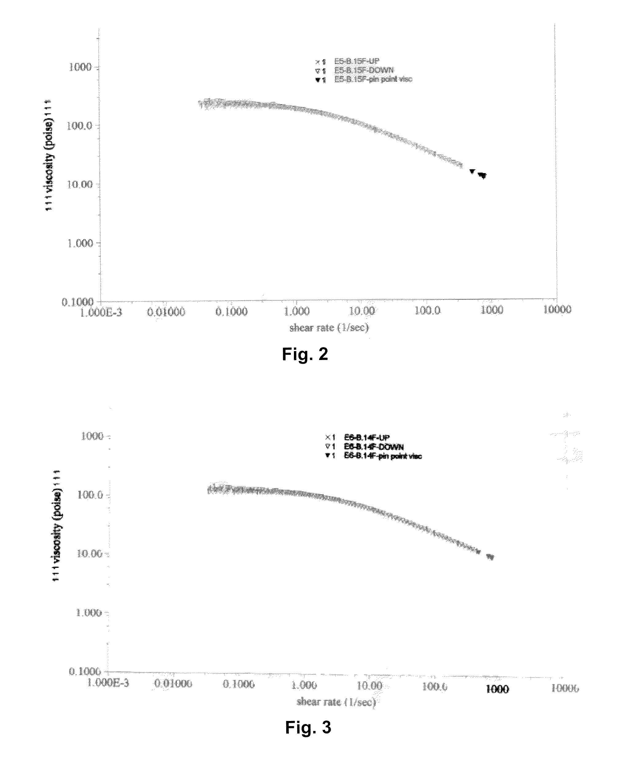
[0048]An electrolyte was formed by dissolving 3.18 grams of LiClO4 (Sigma Aldrich) in 10 milliliters of dry propylene carbonate (Sigma Aldrich). Separately, 1 gram of poly(propylene carbonate) (Sigma-Aldrich) and 2 grams of poly(ethylene oxide) (Sigma-Aldrich) were each dissolved in 10 milliliters of propylene carbonate. The poly(propylene carbonate) was then mixed with the poly(ethylene oxide) solution, which resulted in a viscous clear solution that did not exhibit phase separation. The LiClO4 solution was thereafter added to the polymer mixture to form a clear electrolyte, which was then cooled to room temperature. The viscosity of the resulting electrolyte was recorded by placing 1 ml onto a 4-cm plate in a plate-plate (Model AR1000 Thermal Analysis and Rheology) rheometer. The results are shown in FIG. 2. At 1 sec−1, the viscosity was 34 poise (at 25° C.).

example 2

[0049]An electrolyte was formed as described in Example 1, except that 1.5 grams of poly(propylene carbonate) and 1.5 grams of poly(ethylene oxide) were employed. The viscosity of the resulting electrolyte was recorded by placing 1 ml onto a 4-cm plate in a plate-plate (Model AR1000 Thermal Analysis and Rheology) rheometer. The results are shown in FIG. 3. At 1 sec−1, the viscosity was 120 poise (at 25° C.).

example 3

[0050]An electrolyte was formed as described in Example 1, except that 2 grams of poly(propylene carbonate) and 1 gram of poly(ethylene oxide) were employed. The viscosity of the resulting electrolyte was recorded by placing 1 ml onto a 4-cm plate in a plate-plate (Model AR1000 Thermal Analysis and Rheology) rheometer. The results are shown in FIG. 4. At 1 sec−1, the viscosity was 181 poise (at 25° C.).


PUM


Abstract

An electrolytic capacitor that contains an anodically oxidized porous anode, cathode, and an electrolyte that contains an alkali metal salt and ionically conductive polymer is provided. The alkali metal salt forms a complex with the ionically conductive polymer and thereby improves its ionic conductivity, particularly at higher temperatures. The electrolyte also contains an organic solvent that reduces the viscosity of the electrolyte and helps lower the potential barrier to metal ion transport within the electrolyte to improve conductivity. By selectively controlling the relative amount of each of these components, the present inventors have discovered that a highly ionically conductive electrolyte may be formed that is also in the form of a viscous liquid. The liquid nature of the electrolyte enables it to more readily enter the pores of the anode via capillary forces and improve specific capacitance. Further, although a liquid, its viscous nature may inhibit the likelihood of leakage.

Description

BACKGROUND OF THE INVENTION[0001]Electrolytic capacitors are increasingly being used in the design of circuits due to their volumetric efficiency, reliability, and process compatibility. Electrolytic capacitors typically have a larger capacitance per unit volume than certain other types of capacitors, making them valuable in relatively high-current and low-frequency electrical circuits. One type of capacitor that has been developed is a wet electrolytic capacitor that includes an anode, a cathode current collector (e.g., aluminum can), and a liquid electrolyte. Liquid electrolytes are advantageous due to the potential to reach high ionic conductivity. However, such an electrolyte has its drawbacks as well. For example, a separator material (e.g., fabric or paper) is often required not only to retain the liquid electrolyte between the anode and cathode, but also to maintain a constant distance between the electrodes. This is particular important for high voltage and high reliability ...

Claims


Application Information

Patent Timeline
Patent Type & Authority Patents(United States)
IPC IPC(8): H01G9/00
CPCH01G9/035H01G9/145H01G9/052H01G9/022
Inventor DREISSIG, DIRK H.GALVAGNI, JOHN
Owner AVX CORP
Learn More