Torque coupling for rotary-wing aircraft

a technology of rotary-wing aircraft and torque coupling, which is applied in the direction of rotors, marine propulsion, vessel construction, etc., can solve the problems of significant disadvantages in configuration, oscillatory drive forces, and unsatisfactory vibration or other effects of rotor components, so as to reduce size and weight, high torque capacity, and the effect of increasing stability in the rotor

Active Publication Date: 2012-07-24
TEXTRON INNOVATIONS
View PDF8 Cites 20 Cited by
  • Summary
  • Abstract
  • Description
  • Claims
  • Application Information

AI Technical Summary

Benefits of technology

[0006]Therefore, it is an object of the present invention to provide an improved torque coupling that provides for kinematic scissoring motion to relieve kinematic binding in rotor heads of rotary-wing aircraft.
[0008]The present invention provides for several advantages, including: (1) high-torque capacity; (2) reduced size and weight; and (3) more stability in a rotor of a tiltrotor aircraft when the rotor is oriented in airplane mode.

Problems solved by technology

Unfortunately, various forces can be produced within the rotor head assembly, leading to undesirable vibration or other effects encountered by components of the rotor head.
One example of an undesirable effect is a “scissors” binding within prior-art designs, this binding causing oscillatory drive forces.
Whereas the Zoppitelli device may provide for relief of the oscillatory drive forces, the configuration has significant disadvantages.
For example, the assembly is large, which reduces the volume available in the hub for rotating controls.
In addition, the assembly is relatively heavy, which is particularly undesirable in a rotary-wing aircraft.

Method used


Image

  • Torque coupling for rotary-wing aircraft
  • Torque coupling for rotary-wing aircraft
  • Torque coupling for rotary-wing aircraft

Examples


Embodiment Construction

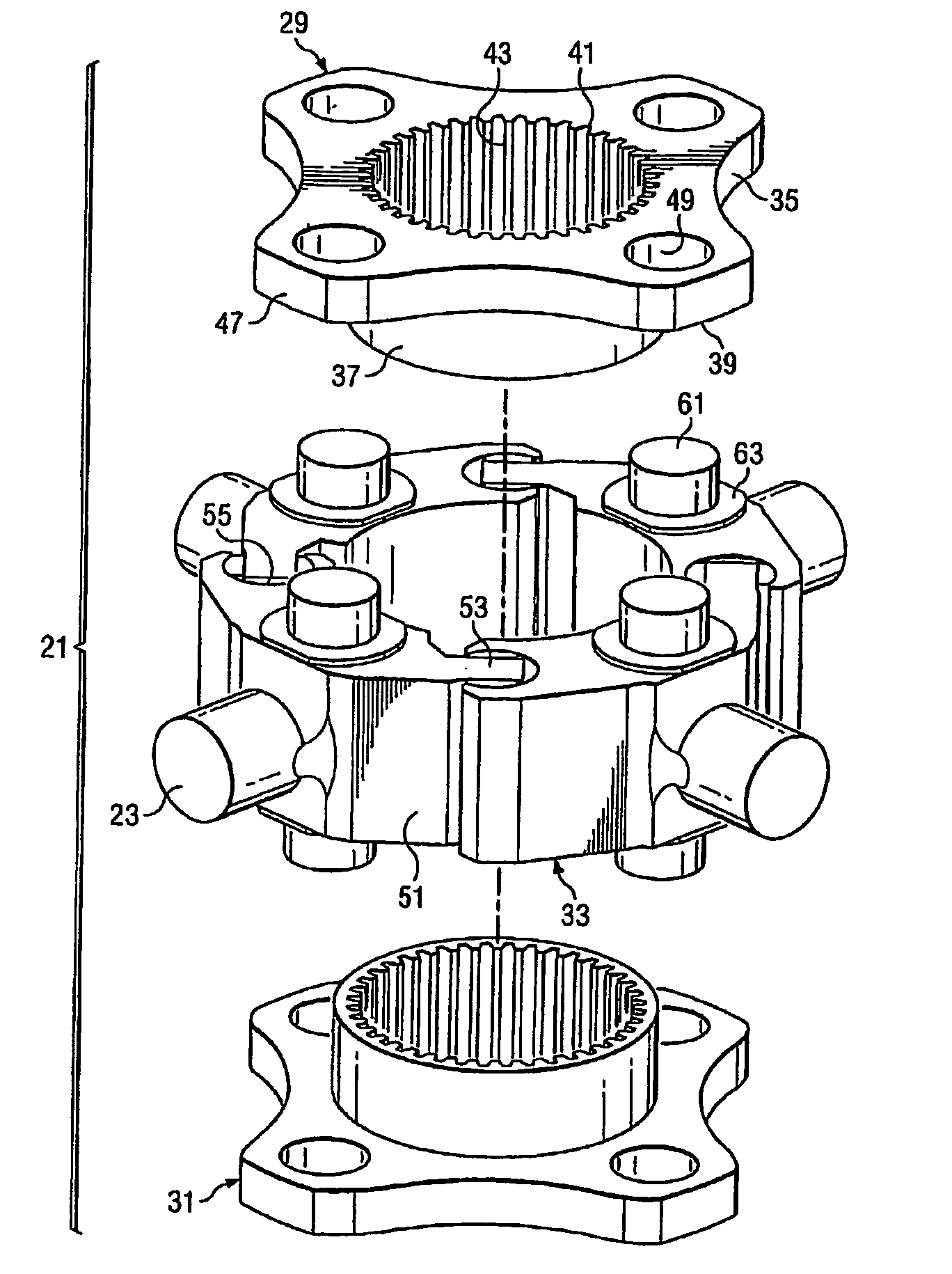
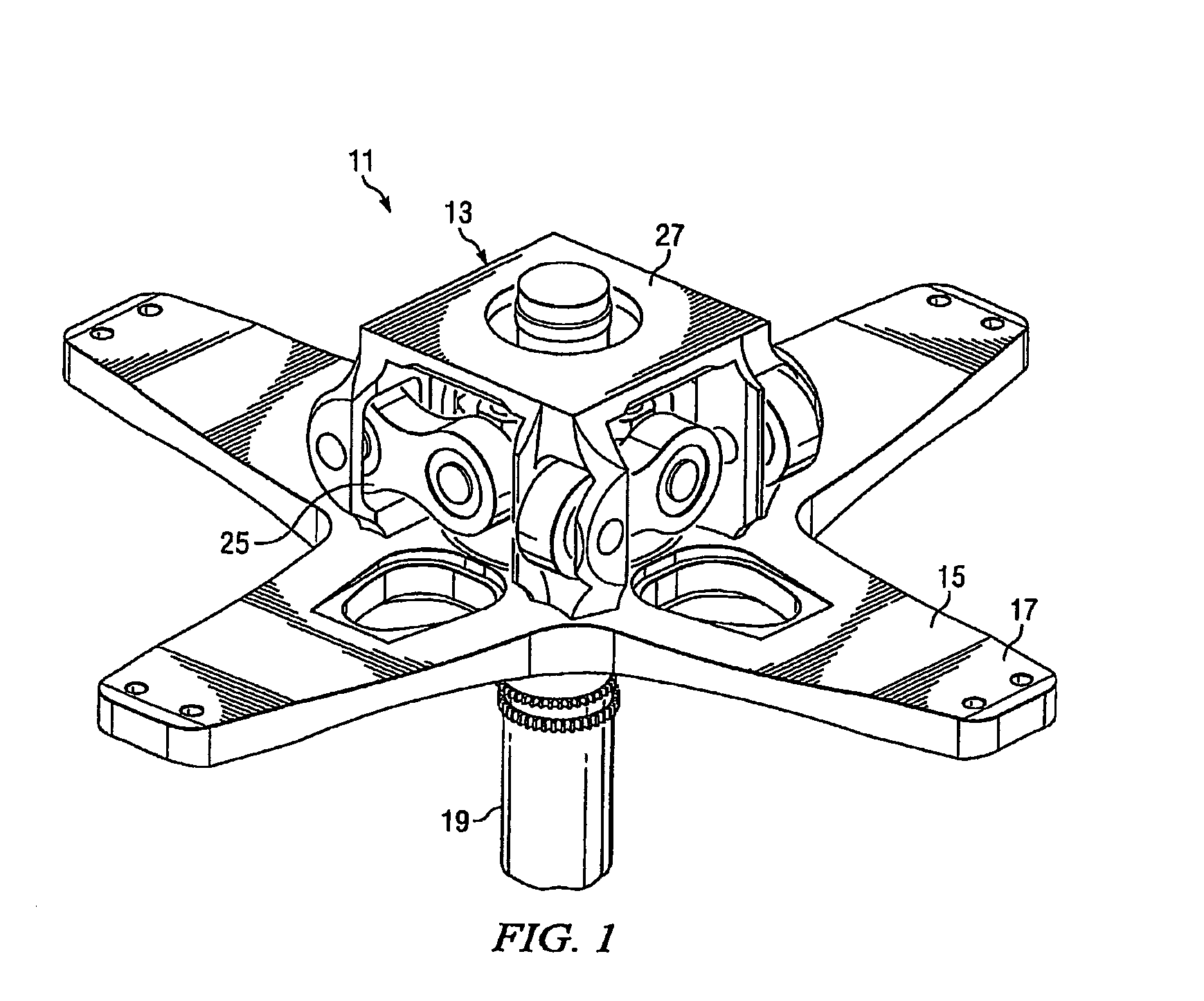
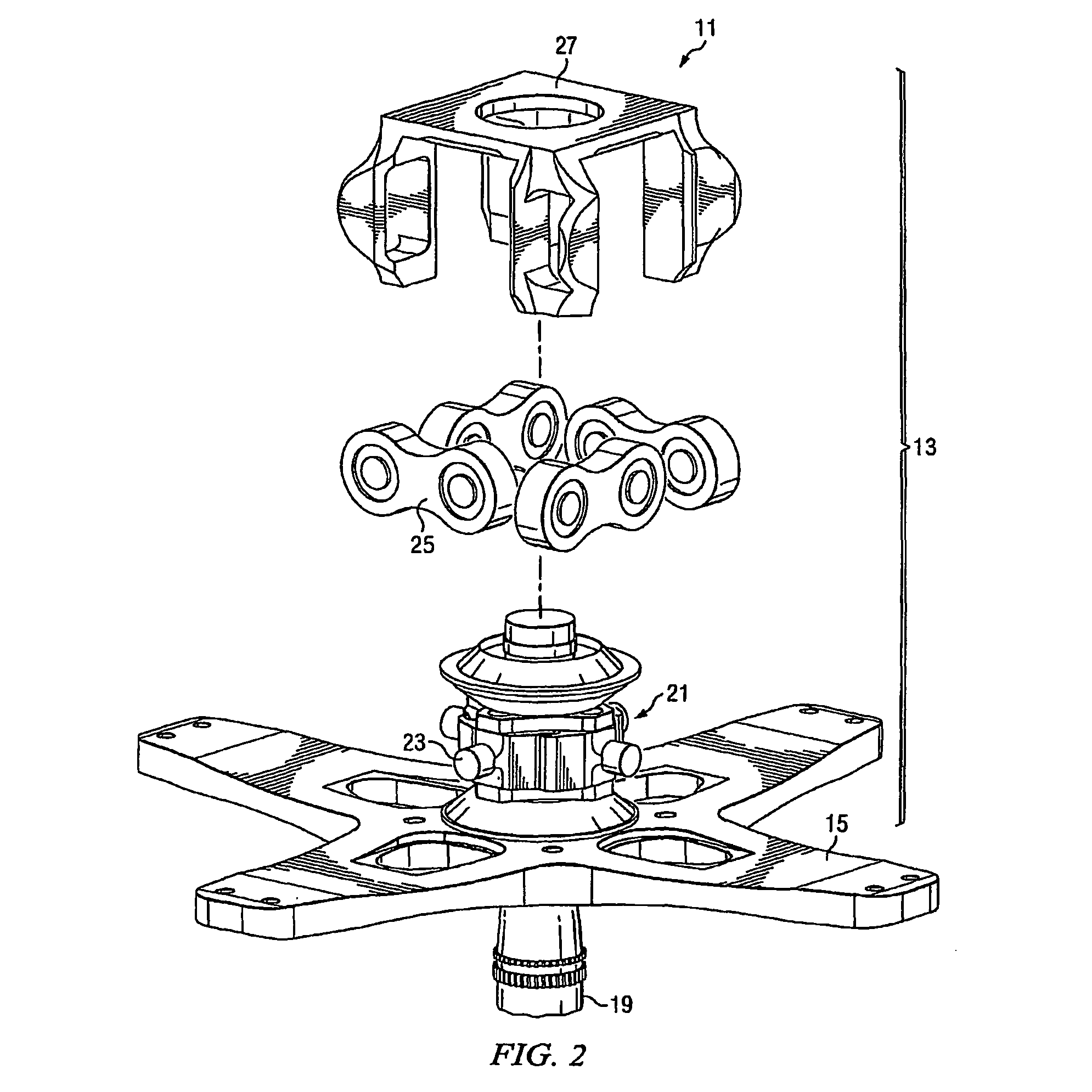
[0018]The present invention provides a high-torque coupling adaptable for use in a rotor head of a rotary-wing aircraft. The coupling provides for a kinematic scissoring motion that relieves the kinematic binding which causes oscillatory drive forces in previous designs. Also, the coupling of the invention has the advantages of reduced size and reduced weight over previous designs. The reduced size allows for maximizing the envelope for the rotating controls, resulting in more favorable control system coupling terms and, when used in the hub of a tiltrotor aircraft, a more stable rotor hub in airplane mode.

[0019]Referring to the figures, FIGS. 1 and 2 show a rotor head 11 for a rotary-wing aircraft, rotor head 11 incorporating a torque coupling 13 according to the present invention. Rotor head 11 comprises coupling 13 and a yoke 15 rigidly mounted to coupling 13 for rotation with coupling 13. Yoke 15 is configured to allow for rotor blades (not shown) to be attached to outer portion...


PUM


Abstract

A torque coupling (13) for a rotor head (11) of a rotary-wing aircraft has upper and lower plates (29, 31) configured for rotation with a rotor mast (19). Drive links (33) pivotally connected to the upper and lower plates (29, 31) pivot about a pivot axis generally parallel to and radially offset from an axis of rotation of the plates. Each link (33) is engaged with adjacent drive links (33) to form a continuous ring of links, such that motion of one link (33) about its pivot axis causes motion in an opposite direction of each adjacent link (33) about its pivot axis. Drive elements (25) connect the drive links (33) to an assembly configured to receive rotor blades. The drive elements (25) may be components of a universal joint, a multiple trailing-link configuration, a pad-bearing configuration, or another type of articulating assembly.

Description

TECHNICAL FIELD[0001]The present invention relates generally to torque couplings and relates particularly to torque couplings used in rotor heads of rotary-wing aircraft.DESCRIPTION OF THE PRIOR ART[0002]Rotor heads of rotary-wing aircraft, such as helicopters and tiltrotors, are rotated using a rotor mast. Unfortunately, various forces can be produced within the rotor head assembly, leading to undesirable vibration or other effects encountered by components of the rotor head. One example of an undesirable effect is a “scissors” binding within prior-art designs, this binding causing oscillatory drive forces.[0003]One method for relieving these forces is shown in U.S. Pat. No. 6,712,313 to Zoppitelli, et al., in which a driving disk rotates with a rotor mast and is connected to each of two driven disks on either side of the driving disk by at least one connecting pin. Each pin is hinged to each of the disks by one of three ball joint connections, and each of the driven disks is conne...

Claims


Application Information

Patent Timeline
Patent Type & Authority Patents(United States)
IPC IPC(8): B64C27/32
CPCB64C27/32
Inventor STAMPS, FRANK B.RAUBER, RICHARD
Owner TEXTRON INNOVATIONS
Why Eureka
Try Eureka