Suction catheter and suction-catheter system

a technology of suction catheter and suction catheter, which is applied in the field of suction catheter, can solve the problems of not having the ability to remove blood clots easily and smoothly, and the product with the obliquely formed leading end portion does not have the ability to meet the above-mentioned requirements, so as to achieve the effect of convenient and smooth removal and an obj

Active Publication Date: 2012-07-31
TAKUMA NORIKATA
View PDF12 Cites 167 Cited by
  • Summary
  • Abstract
  • Description
  • Claims
  • Application Information

AI Technical Summary

Benefits of technology

[0020]The above-described circumstances have led us to make the present invention. Accordingly, an object of the present invention is to provide a suction catheter that is capable of retrieving and removing, easily and smoothly, an object, such as a blood clot, formed inside a blood vessel from the blood vessel without allowing the flowing-away of the object down the stream. Another object of the present invention is to provide a suction-catheter system that allows the above-mentioned suction catheter to operate efficiently.
[0034]For this reason, the aspects of the present invention can provides a suction catheter that is capable of retrieving and removing, easily and smoothly, an object, such as a blood clot, formed inside a blood vessel from the blood vessel without allowing the flowing-away of the object down the stream.

Problems solved by technology

Likewise, the product with an obliquely-formed leading-end portion does not have an enough ability to easily and smoothly remove a blood clot.
None of the suction catheters that have been proposed thus far satisfies all the above-mentioned requirements.

Method used


Image

  • Suction catheter and suction-catheter system
  • Suction catheter and suction-catheter system
  • Suction catheter and suction-catheter system

Examples


first embodiment

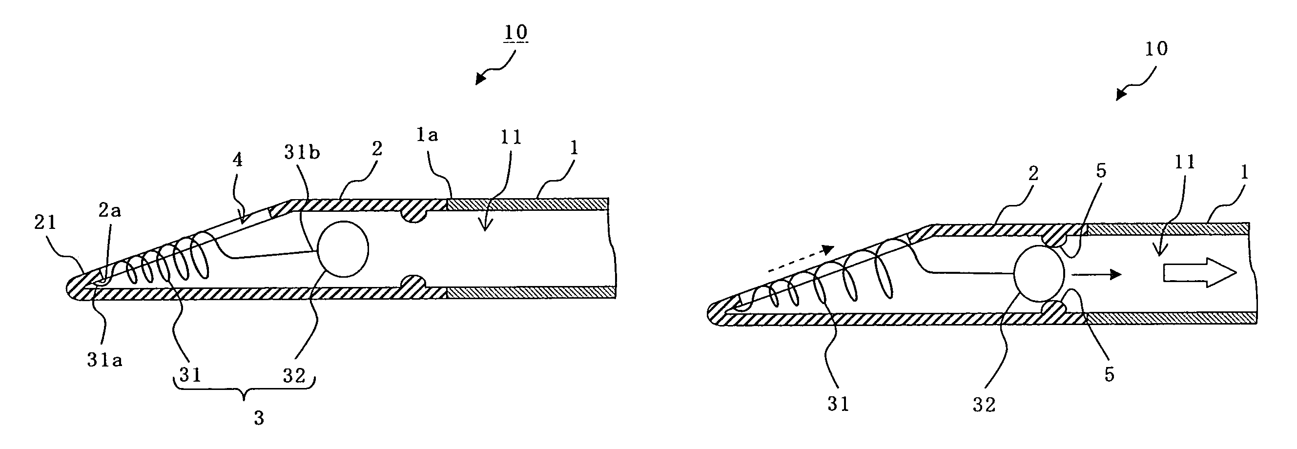
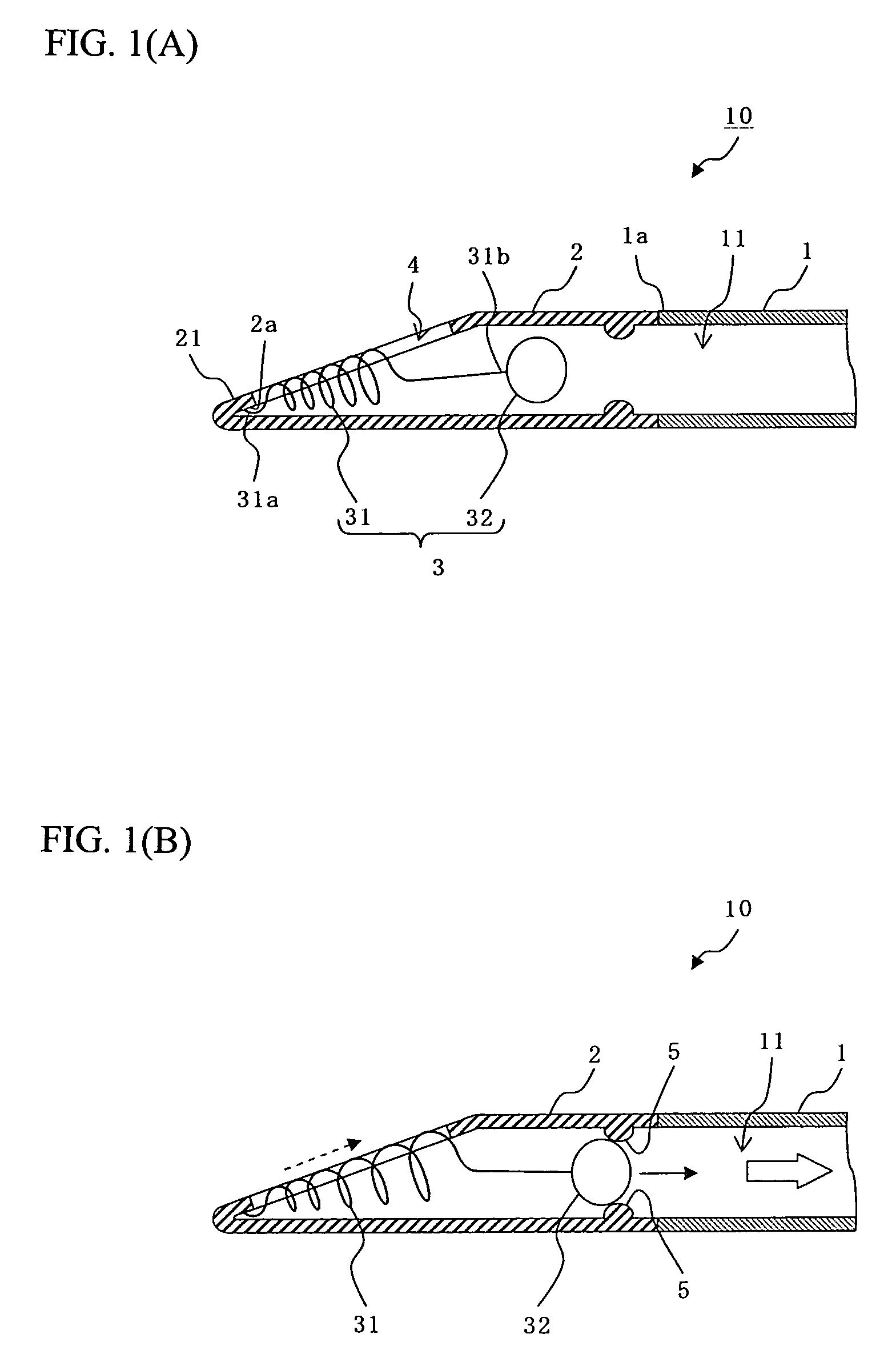
[0052]FIGS. 1A and 1B are drawings each of which illustrates a suction catheter according to the present invention. FIG. 1A is a schematic sectional view illustrating the suction catheter before its action. FIG. 1B is a schematic sectional view illustrating the suction catheter after its action.

[0053]As FIGS. 1A and 1B show, a suction catheter 10 according to this first embodiment includes: a catheter main body 1; a leading-end case portion 2 positioned at a leading-end portion 1a of the catheter main body 1; and object cutting means 3 installed in the leading-end case portion 2.

[0054]The catheter main body 1 is a flexible lengthy body with a lumen 11 formed inside the main body. The catheter main body 1 with such a structure is capable of following sufficiently the bending of the blood vessel.

[0055]The catheter main body 1 can be made of various materials. Some examples of such materials are: polyvinyl chloride; polyethylene; polypropylene; polyurethane; ethylene-propylene copolyme...

second embodiment

[0089]The suction catheter of the present invention can be modified for the purpose of allowing the suction catheter to be efficiently inserted into the blood vessel and of allowing the leading end of the suction catheter to reach the lesion (the blood clot) easily. To put it differently, a suction catheter of this second embodiment differs from the suction catheter of the above-described first embodiment in that the suction catheter of the second embodiment is provided with means for assisting the insertion of suction catheter.

[0090]Incidentally, when each of the following embodiments is described, the description to be given focuses mainly on the points that differ between each of the following embodiments and the above-described first embodiment. For those constituent parts that are common to each of the following embodiments and the above-described first embodiment, the same reference numerals that are used in the first embodiment will be given in each of the following embodimen...

third embodiment

[0093]The suction catheter of the present invention can be modified for the purpose of allowing the driving means to give the power that is not the sucking force to the object cutting means. To put it differently, a suction catheter of this third embodiment differs from the suction catheter of the above-described first embodiment in that the suction catheter of this third embodiment is provided with driving means that is not a suction apparatus.

[0094]As FIG. 6 shows, a suction catheter 30 according to this third embodiment includes: a catheter main body 1; a leading-end case portion 2 positioned at a leading-end portion 1a of the catheter main body 1; and object cutting means 13 installed in the leading-end case portion 2.

[0095]The object cutting means 13 is made, either partially or entirely, of a magnetic material, and includes, for example, a cutting portion 31 exposed through an opening 4 and a power receiving portion 33. The power receiving portion 33 moves the cutting portion ...


PUM


Abstract

Provided is a suction catheter including: a catheter main body made of a flexible lengthy body having a lumen inside; a leading-end case portion positioned at a leading-end portion of the catheter main body and including an opening for retrieving an object; and object cutting means partially exposed through the opening and movable in the axial direction within the leading-end case portion. The object cutting means includes a cutting portion exposed through the opening portion, and a power receiving portion driving the cutting portion when receiving power from outside. A leading-end side of the suction catheter is inserted into a blood vessel while a base-end portion of the suction catheter is connected to a suction apparatus. An object sticking to the internal wall of the blood vessel is cut off by operating the object cutting means in the opening of the leading-end case portion while the lumen is vacuumed. The cut-off object is immediately sucked in and retrieved.

Description

BACKGROUND OF THE INVENTION[0001]1. Field of the Invention[0002]The present invention relates to a suction catheter used in a treatment where the suction catheter is inserted into a blood vessel to suck out and remove an object such as a blood clot therefrom. Specifically, the present invention relates to a technique that is used when objects cause an occluded blood-vascular system, such as in the case of cerebral infarction or myocardial infarction, for the purpose of retrieving and removing the objects, easily and smoothly, from the blood vessel without allowing the objects to flow down the stream.[0003]2. Description of the Related Art[0004]A number of diseases are known to be caused by an occluded blood vessel. For example, each of the cerebral infarction and the myocardial infarction is a disease caused by an occluded arterial system of the corresponding organ. An economy-class syndrome is a potentially fatal disease that is caused by an occluded pulmonary blood vessel due to a...

Claims


Application Information

Patent Timeline
Patent Type & Authority Patents(United States)
IPC IPC(8): A61M1/00
CPCA61B17/22004A61B17/320783A61B2017/22079A61B2017/00876A61B2017/32004A61B2017/00398A61B2017/320008
Inventor TAKUMA, NORIKATA
Owner TAKUMA NORIKATA
Why Eureka
Try Eureka