
Controller of electric motor having function of estimating inertia and friction simultaneously

a technology of electric motor and function, which is applied in the direction of program control, non-deflectible wheel steering, record information storage, etc., can solve the problems of difficult to precisely identify inertia and friction of the driven body, difficult to precisely perform this for a short time, and deteriorate the estimation accuracy of inertia. achieve the effect of improving the estimation accuracy of inertia

Active Publication Date: 2012-07-31
FANUC LTD
View PDF18 Cites 4 Cited by
  • Summary
  • Abstract
  • Description
  • Claims
  • Application Information

AI Technical Summary

Benefits of technology

The present invention provides a controller for an electric motor that can simultaneously estimate the inertia and friction of the motor. This is achieved by adding a sine wave instruction and an electric current feedback value to the controller. The estimated inertia and friction can be used to improve the accuracy of the inertia estimation. The estimated electric current value is calculated by adding the speed feedback value and the electric current feedback value in every sampling period. The estimated inertia and friction can be used to configure a disturbance observer which calculates estimated disturbance torque from the electric current feedback value and the estimated electric current value. The estimated inertia and friction can also be used to update the inertia and viscous friction of the motor shaft in real-time. Overall, the present invention provides a more accurate and efficient controller for electric motors.

Problems solved by technology

When there is torque offset as in the case of a gravitational axis to which a fixed force is applied or large Coulomb friction, the estimation accuracy of inertia is deteriorated.
When the configuration of the driven body is complicated, it is not easy to precisely identify inertia and friction of the driven body.
It is not easy to precisely perform this for a short time.
The technique is not easily applied to the machine tool to which the operation range is limited.
Although viscous friction can be estimated, Coulomb friction cannot be estimated.
A large amount of data memory is necessary.
However, when friction is large, the estimation accuracy of inertia is lowered.

Method used


Image

  • Controller of electric motor having function of estimating inertia and friction simultaneously
  • Controller of electric motor having function of estimating inertia and friction simultaneously
  • Controller of electric motor having function of estimating inertia and friction simultaneously

Examples


Embodiment Construction

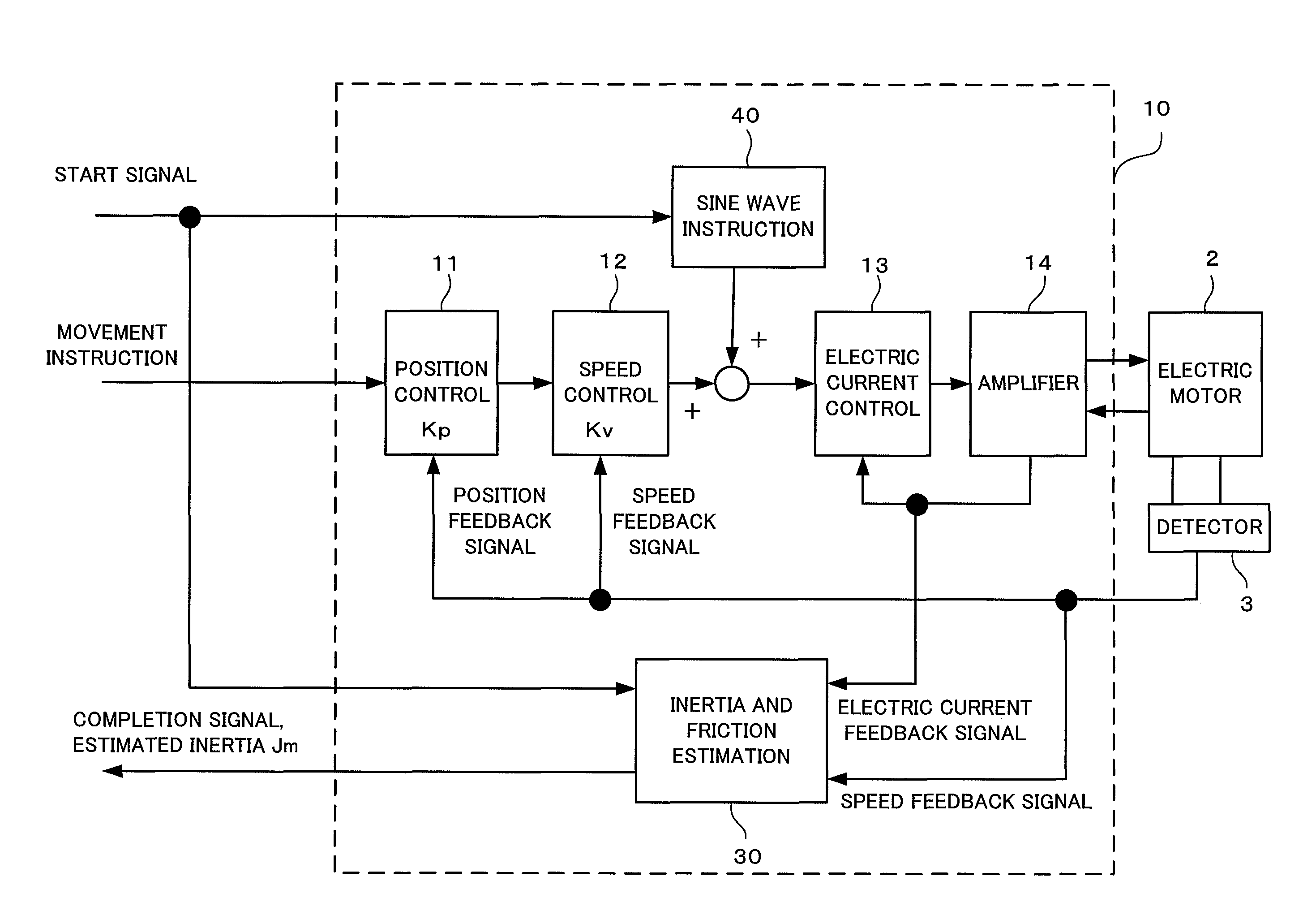
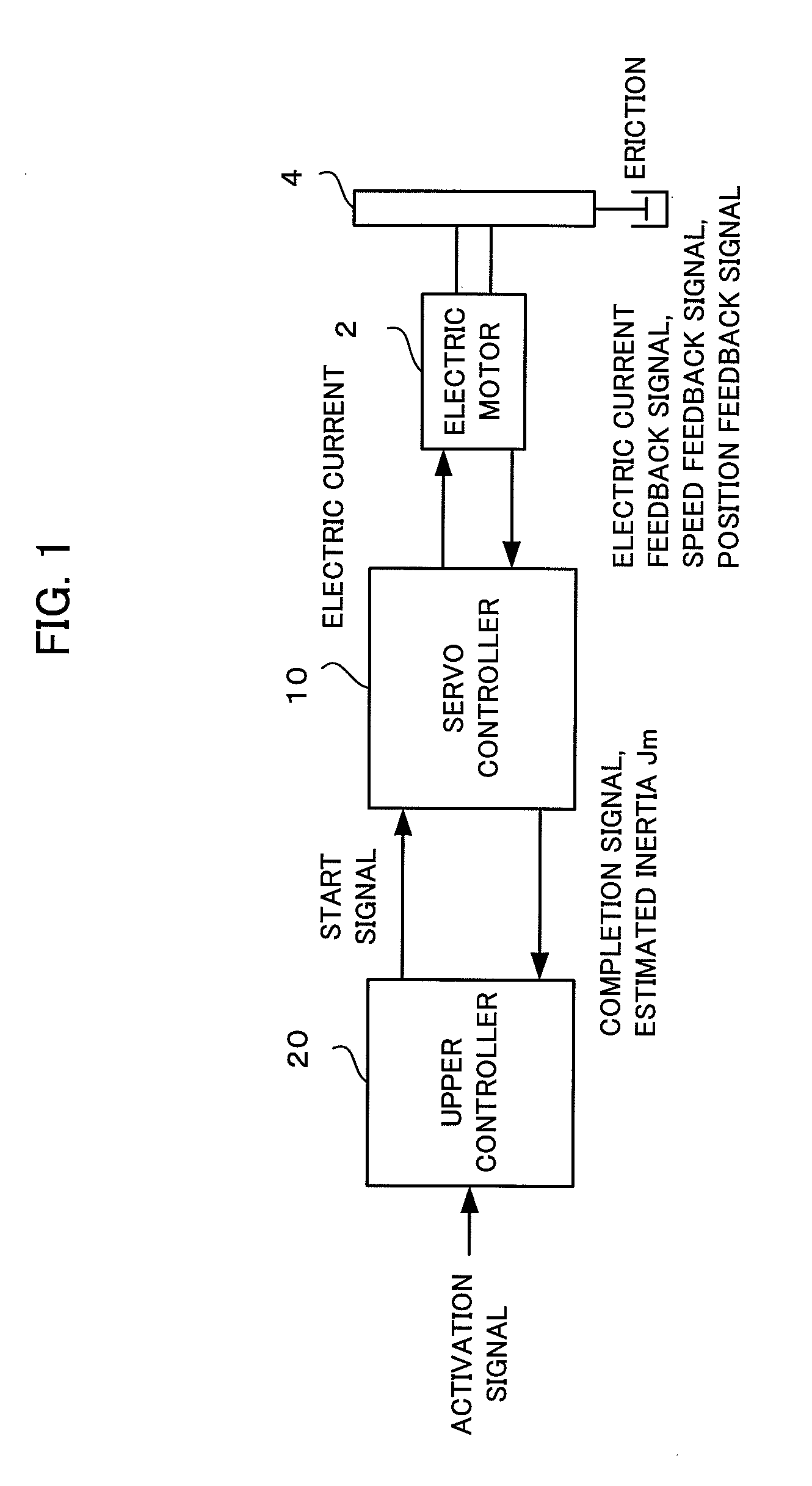
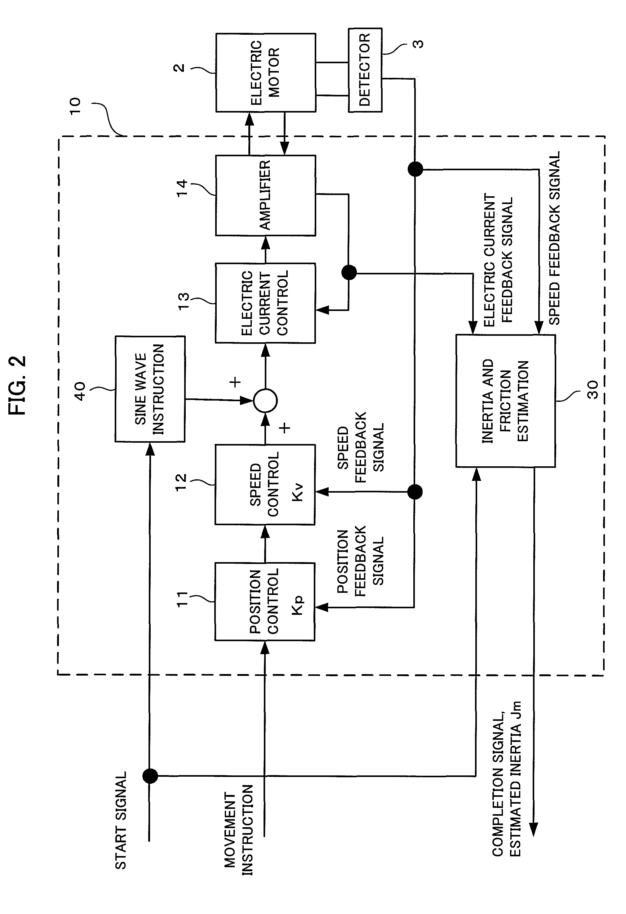
[0051]FIG. 1 is a block diagram showing the schematic configuration of a control system including an embodiment of a controller according to the present invention.

[0052]As shown in FIG. 1, in an embodiment (a servo controller 10) of the controller according to the present invention, an electric motor 2 operating a driven body 4 is a control target. The electric motor 2 is a driving source which changes the position and posture of a table holding a workpiece in a machine tool or is used as a driving source for rotationally operating a robot arm. The driven body 4 includes the table and the robot arm holding a workpiece in a machine tool, the workpiece attached to or detached from the table or the arm, and the operating section of the electric motor 2 itself. The driven body 4 has friction characteristic including viscous friction and Coulomb friction.

[0053]The position, speed, and torque of the electric motor 2 are controlled by the servo controller 10. The servo controller 10 is con...


PUM


Abstract

A controller estimates Coulomb friction itself together with inertia and viscous friction, and reduces the influence of the Coulomb friction on the accuracy of the estimated inertia. In addition, the controller estimates inertia, viscous friction and Coulomb friction simultaneously with sequential adaptation in which a Fourier transformer is not used but an inverse transfer function model is used in order to minimize the estimated error. Data sampled for a predetermined time need not be accumulated, as a result, a large amount of data memory is unnecessary.

Description

RELATED APPLICATION DATA[0001]This application claims priority under 35 U.S.C. §119 and / or §365 to Japanese Application No. 2009-197652 filed Aug. 28, 2009, the entire contents of which are incorporated herein by reference.BACKGROUND OF THE INVENTION[0002]1. Field of the Invention[0003]The present invention relates to a controller of an electric motor which drives a drive shaft of a machine tool or an industrial machine. More specifically, the present invention relates to a controller of an electric motor having the function of estimating inertia and friction of its drive shaft simultaneously.[0004]2. Description of the Related Art[0005]It is important to identify the magnitudes of the inertia, viscous friction, and Coulomb friction of a driven body of a machine tool driven by an electric motor for determining the processing conditions of the machine tool and for precisely controlling a drive shaft driven by the electric motor.[0006]For instance, in the determination of the time con...

Claims


Application Information

Patent Timeline
Patent Type & Authority Patents(United States)
IPC IPC(8): G05B1/06H02P29/00
CPCG05B19/404H02P23/14G05B2219/41163
Inventor OKITA, TADASHITOYOZAWA, YUKIOSONODA, NAOTO
Owner FANUC LTD
Learn More