Intervertebral prosthesis for supporting adjacent vertebral bodies enabling the creation of soft fusion and method

a technology of intervertebral discs and adjacent vertebrae, applied in the field of methods and interbody discs, can solve the problems of abnormal load on adjacent structures, not being able to be corrected or favorable for all movements, and showing some success but also failures

Active Publication Date: 2012-08-07
THOMAS HAIDER PATENTS
View PDF56 Cites 13 Cited by
  • Summary
  • Abstract
  • Description
  • Claims
  • Application Information

AI Technical Summary

Benefits of technology

[0010]A desirable condition, which I term soft fusion, can be created between a patient's adjacent vertebral bodies in which the natural disc has failed in whole or in part by a) removing the failed disc or failed portion thereof; b) installing an artificial intervertebral disc between the two vertebral bodies; c) the disc providing one or more selected continuous or discontinuous channels of limited size for bone to form and fuse into one or more continuous or discontinuous struts between the vertebral bodies; d) the device being stiff enough to support the bodies in their natural spaced relationship while allowing limited motion and flexible enough to transfer sufficient energy to the bone struts to create one or more conditions of nonunion joints or pseudoarthrosis resulting in living nonrigid bone growth; and e) the disc being further arranged to limit its movement to an amount which is sustainable by the disc without resulting in fatigue failure during an anticipated lifetime.

Problems solved by technology

This type of procedure when successfully completed, will result in a large bone mass between the vertebral bodies which will stabilize the column to a fixed position.
The success of a rigid fusion procedure appears to be one of many causes of adjacent segment disease.
These have shown some success but also failures.
The rotation centers may be favorable at one specific instantaneous center of rotation present in a natural healthy disc, but is never correct nor favorable for all movements.
This forces abnormal loads on adjacent structures.
Materials needed for a stable ball and socket device are often very stiff or incompressible, thus any axial loads and especially shock loads through the device are almost completely transferred to the adjacent structures.
A patient expecting a favorable outcome with a ball and socket lumbar disc arthroplasty device may find unfavorable results if repeated axial loads / shocks (along the spine axis) are a common occurrence.
These devices must be sufficiently stiff to support the anatomical average and extreme loads, thus too stiff to provide soft fusion as defined hereinafter.
This device is very soft and may collapse under normal loads and will likely not form bone within the small inner diameters.
However, these devices, as a result of their design, would be soft and very flexible resulting in artificial discs capable of absorbing little energy when subjected to shock loads.
Some of the patents / publications do show a vertical hole in the device, but apparently it came about for manufacturing purposes not for functionality.
Such spring arrangements, beside their other problems, such as fracture at attachment points to end plates, provide little shock and energy absorption capability because they either fully compress at normal loads, or fracture at high loads.

Method used


Image

  • Intervertebral prosthesis for supporting adjacent vertebral bodies enabling the creation of soft fusion and method
  • Intervertebral prosthesis for supporting adjacent vertebral bodies enabling the creation of soft fusion and method
  • Intervertebral prosthesis for supporting adjacent vertebral bodies enabling the creation of soft fusion and method

Examples


Embodiment Construction

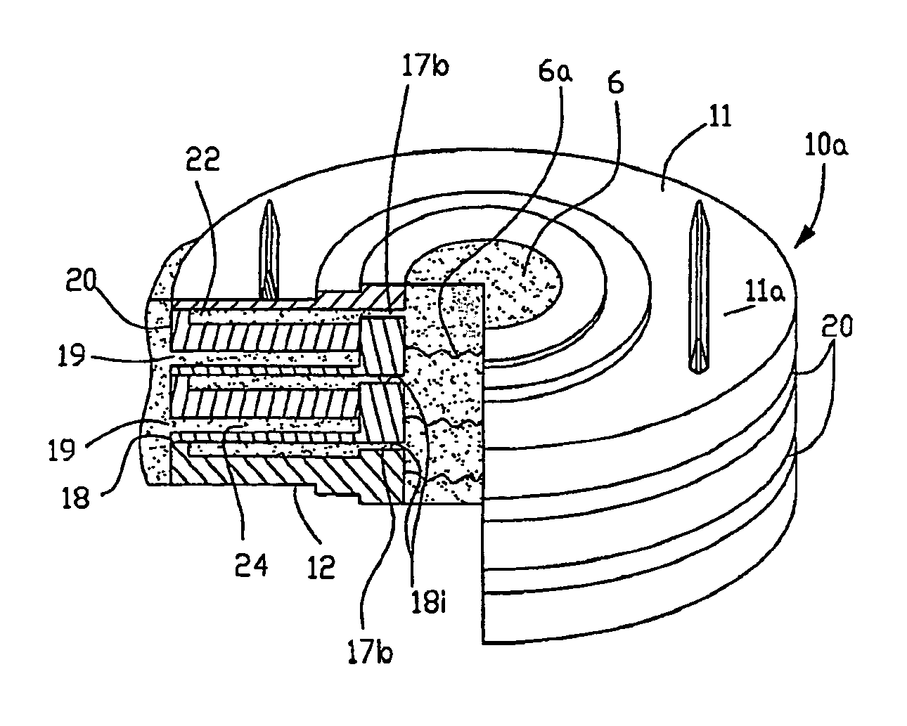
[0083]Referring now to FIG. 3 an upper end plate 11, providing an outer or cephalad surface 11a for buttressing against an upper vertebral body, is joined to a lower end plate 12, providing an outer or caudal surface 12a (not shown in FIG. 3). A group of interlocking interior plates or layers, collectively referred to as 13, are disposed between and joined to the inner surfaces 11b and 12b to form an anterior interbody device or artificial disc. See FIG. 11. The outer surfaces 11a and 12a of the end plates may be provided with an array of mechanical locking features such as the keels 14 or alternative geometric features and fixation rings 15a and 15b. The fixation rings may be constructed of an osteointegrative porous material which abut the edge of a hollow core or bone channel 17. As discussed previously, the core 17 accommodates bone growth to form a continuous or discontinuous strut (with nonunion locations) adjoining the separated vertebral bodies.

[0084]The fixation rings are s...


PUM


Abstract

An intervertebral prosthetic disc for replacing a damaged natural disc includes upper and lower vertebral body engaging surfaces, an exterior wall and one or more generally vertically oriented bone channels of limited cross-sectional area to allow bone to form and fuse into continuous or discontinuous struts between the bodies. The stiffness of the disc, while supporting the bodies, allows the distance therebetween to narrow sufficiently when subjected to a predetermined load such as the patient standing, walking, etc., to transfer sufficient energy to the bone struts to create one or more nonunion joints or pseudoarthrosis at locations along the struts. The disc includes stops to limit the movement thereof to an amount sustainable by the disc without resulting in fatigue failure.

Description

RELATED APPLICATIONS[0001]This application claims priority based on U.S. Provisional Application Ser. No. 60 / 751,182 for a Spinal Motion Restoring Device filed Dec. 16, 2005 (“'182 application”); Ser. No. 60 / 797,731 for a Method of Creating Soft Fusion Between Adjacent Vertebral Bodies and an Interbody Spacer for Accomplishing the Same filed May 4, 2006 (“'731 application”); and 60 / 834,587 for Intervertebral Hybrid Prosthetic Disc filed Aug. 1, 2006 (“'587 application”) for all common subject matter. The contents of said provisional applications are incorporated herein by reference.TECHNICAL FIELD[0002]This application relates to a method and an interbody disc for restoring spinal motion between vertebral bodies between which the natural spinal disc has been removed in whole or in part.BACKGROUND ART[0003]In the field of spinal surgery, many treatment options exist to treat spinal pain, nerve impingement and spinal instability where a natural disc has failed in whole or in part. One...

Claims


Application Information

Patent Timeline
Patent Type & Authority Patents(United States)
IPC IPC(8): A61F2/44
CPCA61F2/442A61F2/4455A61F2/30771A61F2002/2835A61F2002/30092A61F2002/30112A61F2002/30133A61F2002/30153A61F2002/30289A61F2002/30372A61F2002/30405A61F2002/30451A61F2002/30563A61F2002/30566A61F2002/30571A61F2002/30573A61F2002/30594A61F2002/30772A61F2002/30884A61F2002/30971A61F2002/4415A61F2002/4475A61F2002/4629A61F2210/0014A61F2220/0025A61F2220/0033A61F2220/0058A61F2230/0004A61F2230/0015A61F2230/0019A61F2230/0091A61F2310/00011A61F2002/30593
Inventor CORDARO, NICHOLAS M.
Owner THOMAS HAIDER PATENTS
Why Eureka
Try Eureka