Source grating for X-rays, imaging apparatus for X-ray phase contrast image and X-ray computed tomography system

a source grating and imaging apparatus technology, applied in the field of source grating for x-rays, can solve the problems of inability to obtain sufficient brilliance of micro-focus x-ray tubes, difficult to image soft tissue inside a test object, synchrotron radiation has a problem, etc., and achieve the effect of enhancing spatial coheren

Inactive Publication Date: 2012-08-14
CANON KK
View PDF7 Cites 44 Cited by
  • Summary
  • Abstract
  • Description
  • Claims
  • Application Information

AI Technical Summary

Benefits of technology

[0029]Therefore, when a source grating having a small aperture width is to be produced, the aspect ratio (height of the projection part / aperture width of the source grating) becomes large, and it becomes difficult to make such a source grating. Therefore, in the source grating for X-rays of “Phase Retrieval and Differential Phase-Contrast Imaging with Low-Brilliance X-Ray Sources”, F. Pfeiffer et al., April 2006 / Vol. 2 / NATURE PHYSICS, the X-ray transmitting region becomes large due to limitation in the production process, spatial coherence reduces, and blurring may occur in the phase contrast image.
[0032]In view of the above described problem, the present invention has an object to provide a source grating for X-rays which can enhance spatial coherence and is used for X-ray phase contrast imaging, an imaging apparatus for an X-ray phase contrast image and an X-ray computed tomography system.

Problems solved by technology

With this method, an image can be acquired, which that is clearer and easier to see by enhancing the outline of a conventional absorption contrast image, but it is difficult to image soft tissue inside a test object.
However, synchrotron radiation has a problem from a practical point of view.
Therefore, the micro-focus X-ray tube has a problem of being incapable of obtaining a sufficient brilliance depending on the purpose of imaging.

Method used


Image

  • Source grating for X-rays, imaging apparatus for X-ray phase contrast image and X-ray computed tomography system
  • Source grating for X-rays, imaging apparatus for X-ray phase contrast image and X-ray computed tomography system
  • Source grating for X-rays, imaging apparatus for X-ray phase contrast image and X-ray computed tomography system

Examples


embodiment 1

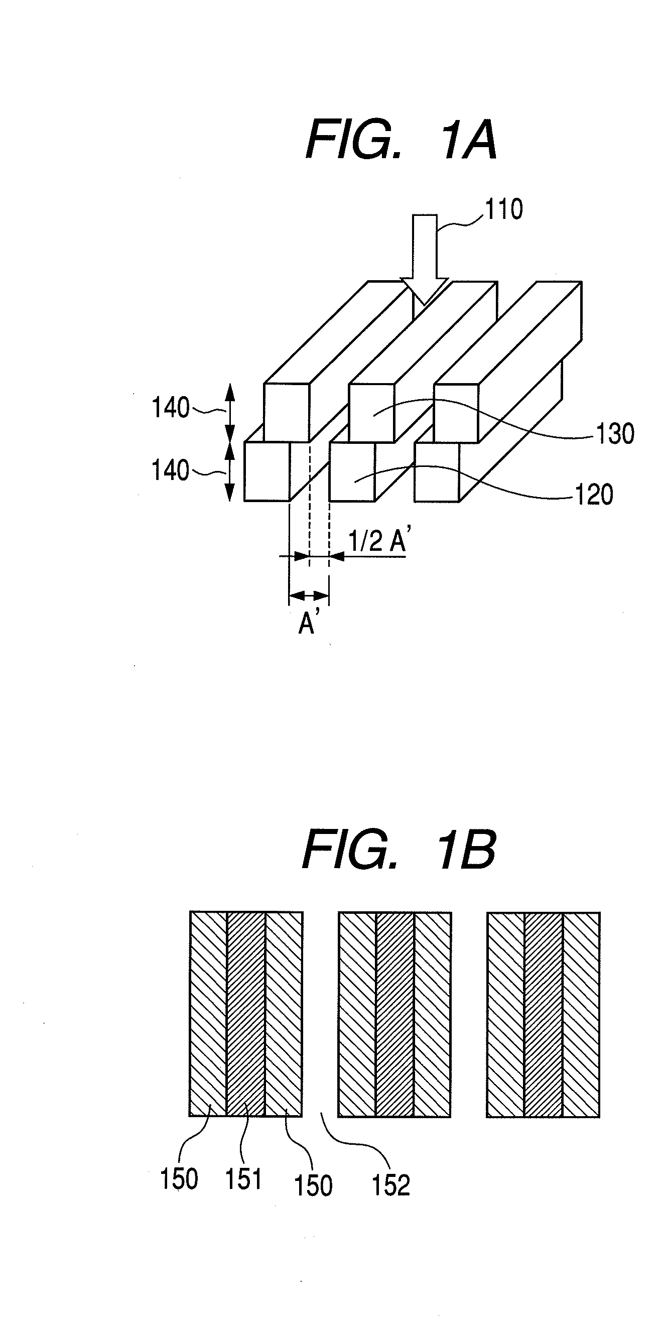
[0044]In embodiment 1, an X-ray source grating will be described. The X-ray source grating has a structure in which an aperture width which is a transmitting region of X-rays formed by an interval between projection parts is made narrower than the aperture width of each of sub-gratings by stacking the line-shaped sub-gratings of two layers by shifting the line-shaped sub-gratings of two layers in a periodic direction with respect to the incident X-rays.

[0045]Here, the sub-grating means a diffraction grating of one layer part which is made by arranging projection parts periodically at constant intervals in the source grating for X-rays configured by being stacked in layers.

[0046]Further, the line-shaped sub-grating indicates the diffraction grating structure of the one layer part in which the linear projecting structures (projection parts) parallel with each other are periodically arranged.

[0047]FIG. 1A illustrates a configuration example of the present embodiment.

[0048]In the presen...

embodiment 2

[0071]In embodiment 2, a configuration example of a variable X-ray transmitting region type source grating will be described. In the variable X-ray transmitting region type source grating, the width of an aperture that is an X-ray transmitting region is made variable by configuring at least one of the individual stacked sub-gratings to be movable.

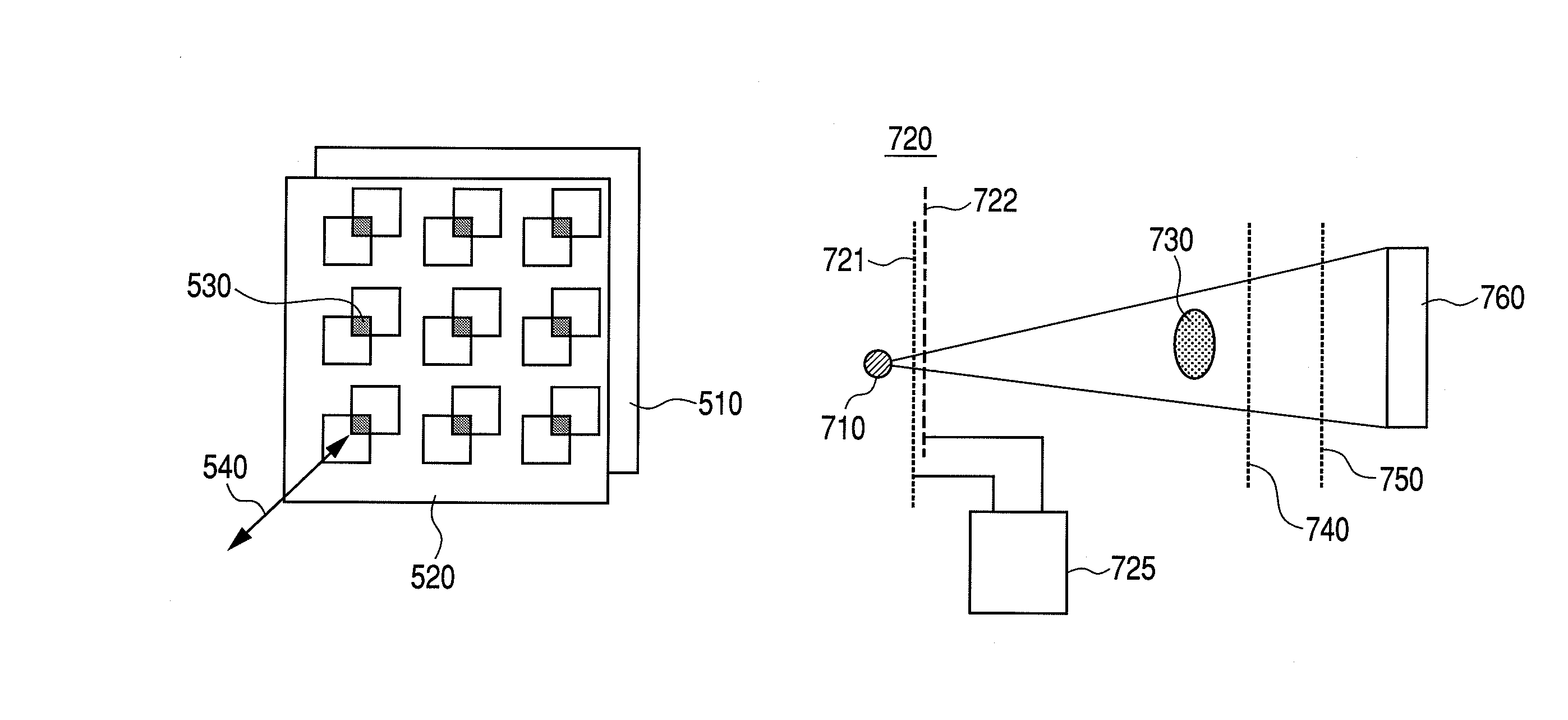
[0072]FIG. 7 illustrates an X-ray imaging apparatus 720 having a movable unit which makes a sub-grating movable. A first sub-grating 721 and a second sub-grating 722 are provided between an X-ray source 710 and a test object 730. Further, a phase grating 740 and an absorption grating 750 are provided between the test object 730 and a detector 760.

[0073]At least one of the first sub-grating 721 and the second sub-grating 722 is made movable by a movable unit 725, and thereby, the X-ray transmitting region is made variable.

[0074]For example, in the one-dimensional source grating for X-rays in embodiment 1, at least one of the line-shaped sub-...

embodiment 3

[0090]In embodiment 3, a configuration example of a source grating will be described. In the source grating, three or more sub-gratings are stacked in layers by shifting the sub-gratings with respect to the sub-gratings in the lower layers in their periodic direction.

[0091]FIG. 6 illustrates a sectional structure of a source grating 600 for X-rays of a three-layer configuration formed by sub-gratings 610, 620 and 630. By staking three or more sub-gratings in layers, the regions for transmitting X-rays can be made narrower as compared with the configuration of two layers.


PUM

PropertyMeasurementUnit
widthaaaaaaaaaa
widthaaaaaaaaaa
thicknessaaaaaaaaaa

Abstract

A source grating for X-rays and the like which can enhance spatial coherence and is used for X-ray phase contrast imaging is provided. The source grating for X-rays is disposed between an X-ray source and a test object and is used for X-ray phase contrast imaging. The source grating for X-rays includes a plurality of sub-gratings formed by periodically arranging projection parts each having a thickness shielding an X-ray at constant intervals. The plurality of sub-gratings are stacked in layers by being shifted.

Description

RELATED APPLICATIONS[0001]The present application is a National Stage Entry of PCT / JP2009 / 057807, filed on Apr. 13, 2009, and claims priority benefit under 35 U.S.C. §119 of Japanese Patent Application No. 2008-105355, filed Apr. 15, 2008, which is hereby incorporated by reference herein in its entirety.TECHNICAL FIELD[0002]The present invention relates to a source grating for X-rays used for X-ray phase contrast imaging, an imaging apparatus for X-ray phase contrast image and an X-ray computed tomography system.BACKGROUND ART[0003]Since the 1990s, research on the phase contrast method using a phase difference of an X-ray beam has been conducted mainly in synchrotron radiation facilities.[0004]Further, research on phase contrast imaging using X-ray tubes in laboratories has also been conducted, and a propagation method, the Talbot interference method, which will be described below, can be performed in principle.[0005]In one propagation method a subject is irradiated with an X-ray be...

Claims


Application Information

Patent Timeline
Patent Type & Authority Patents(United States)
IPC IPC(8): G21K1/06G02B26/06G02F1/017G01T1/36G21K1/10
CPCG21K1/025G21K7/00G21K2207/005
Inventor ITOH, HIDENOSUKEICHIMURA, YOSHIKATSUNAKAMURA, TAKASHIIMADA, AYA
Owner CANON KK
Why Eureka
Try Eureka