Hybrid cable

a hybrid cable and cable technology, applied in the field of hybrid cables, can solve the problems of increasing installation costs, affectingaffecting the performance of the cable, etc., and achieves the effect of reducing the overall flexibility of the cable, reducing and increasing the diameter of the cabl

Active Publication Date:
View PDF7 Cites 34 Cited by
  • Summary
  • Abstract
  • Description
  • Claims
  • Application Information

AI Technical Summary

Benefits of technology

[0023]By dispersing the optical fibre unit among the conductor wires according to the present invention, the conductor wires are the ones which withstand the axial tensile stresses occurring onto the hybrid cable during pulling thereof. Moreover, the conductor wires create a suitable protection for the tight buffer optical fibre unit with respect to the compression forces which act transversally (radially) onto the hybrid cable during installation thereof.
[0024]In particular, the Applicant has found that, when the tight buffer optical fibre unit is inserted among the wires of a conductor of a low voltage power, cable of flexible type, said flexible cable having wires of diameter corresponding to the requirements of Class 5 according to Standard IEC 60228—3rd Edition—2004-11, the conductor wires provide a mechanical protection around the optical fibre unit without forcing the fibre(s) in a pre-fixed position, thereby protecting the fibre(s) from axial and radial stresses acting thereupon.
[0025]The present embodiment is particularly satisfactory when the optical fibre unit is of the tight buffer type, and thus has a reduced diameter (e.g. 900 μm) compared with a “loose buffer” optical fibre unit. A “loose buffer” optical fibre unit is an assembly according to which a tubular element contains one or more optical fibre(s) with an outer diameter of few millimetres. A “loose buffer” optical fibre unit arranged within a power cable provides a protection to the optical fibre(s), but increases the cable diameter and, as a consequence, it decreases the cable overall flexibility. Preferably, the conductor wires of the hybrid cable are in a number from about 16 to about 3300, more preferably from about 24 to about 1800, even more preferably from about 72 to about 238, depending on the desired conductor cross section and chosen wires diameters.
[0026]In the case an already existing power cable has to be replaced, in order to allow an easy installation, the hybrid cable is requested to have a cross-sectional size substantially equal to or very close to that of the power cable previously installed. Therefore, the power cable already present in the building raceway can be uninstalled and replaced with the hybrid cable of the present invention which carries both power and telecommunication data, this operation being less expensive than making the masonry work which is necessary for installing an optical fibre cable in new additional or bigger raceways.

Problems solved by technology

Additional raceways are often needed since the size of the raceways already present in the building—and used for housing the power cables—may not allow an optical fibre cable to be installed together with a power cable within the same raceway.
However, drawbacks arise when further additional raceways or raceways of greater size have to be installed for receiving the optical fibre cables.
For instance, masonry work is generally required to be made in the building / apartments, thereby remarkably increasing the installation costs.
The above mentioned stresses are particularly deleterious to the optical fibres as they can cause attenuation phenomena of the transmitted signal, or can even break or seriously damage the optical fibre during installation of the cable.
However, such a technical solution would be more complex and, moreover, it would cause the cable size to grow to an unacceptable extent, especially in view of the fact that this cable is requested to be installed in a raceway of limited dimensions (and already present in the building structure).
The cable disclosed by document WO 2005 / 114285 is not suitable for installation along tortuous and indefinite paths, as may be required when placing the cable in the raceways of a building.
In fact, along a bend in the cable path, for instance, the optical fibre of the cable according to document WO 2005 / 114285 would tend to maintain its cross-sectional position with respect to the conductor wires, thus undergoing relevant axial / radial stresses which would likely cause an unacceptable deterioration of the data transmission property.

Method used


Image

  • Hybrid cable
  • Hybrid cable

Examples


example

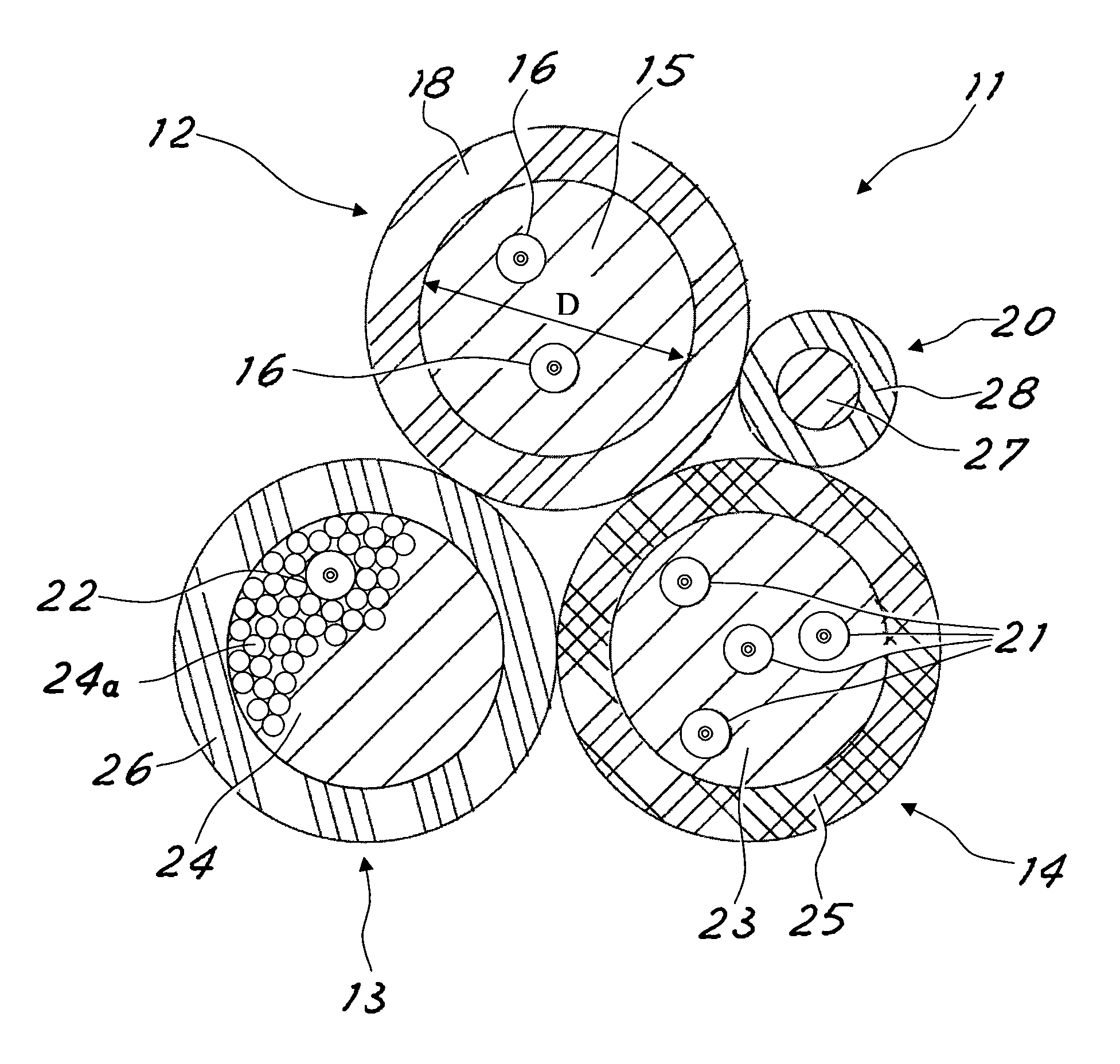
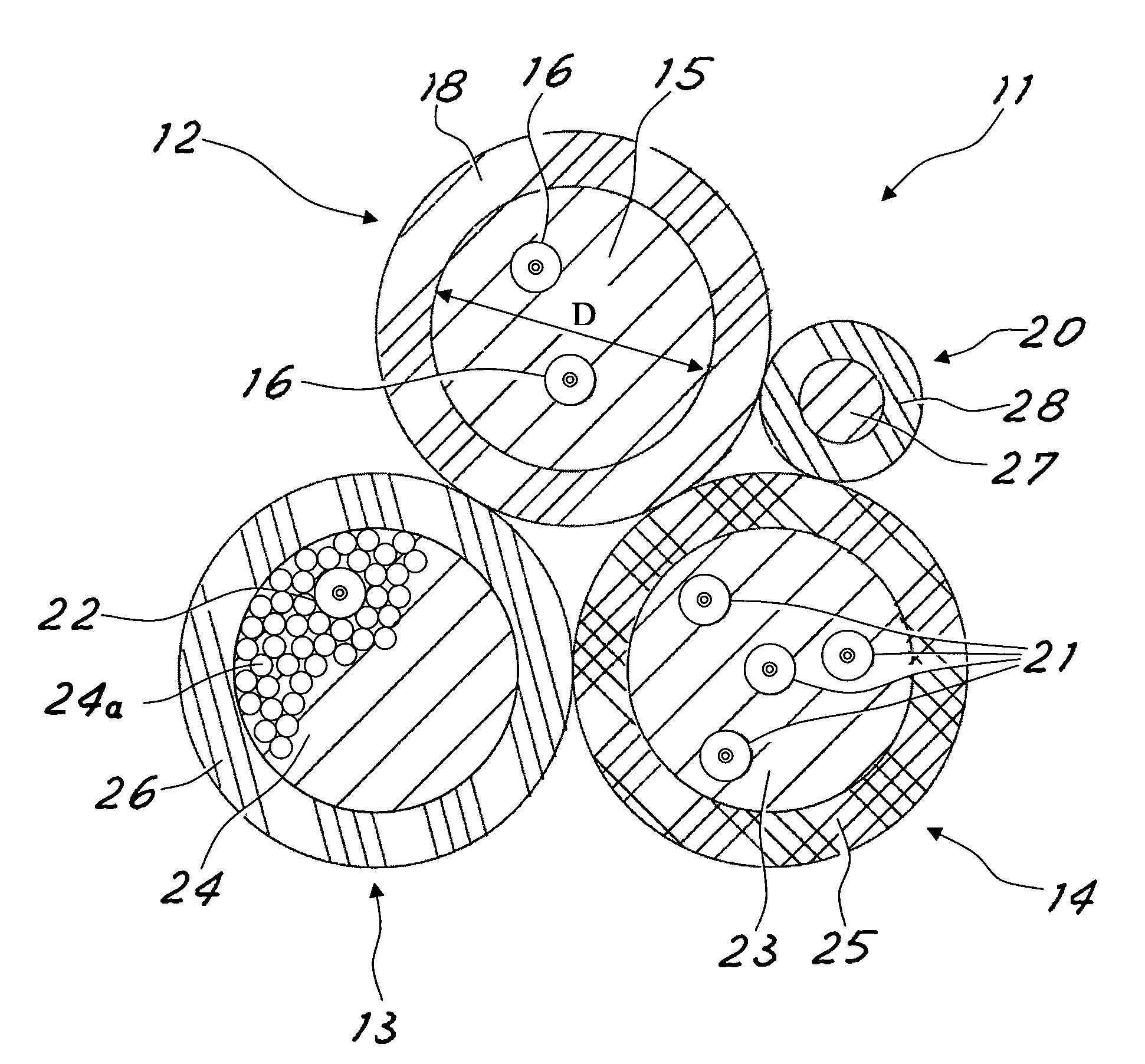
[0042]A three-phase hybrid cable was manufactured, each hybrid phase cable having a cross-section area of 16 mm2 and being formed of 108 copper wires (having a diameter of 0.408 mm) and one optical fibre unit (having diameter of 0.9 mm).

[0043]The optical fibre unit is a tight buffer optical fibre unit, including a single mode or a multi mode optical fibre having a diameter of about 0.25 mm, said optical fibre being coated with a tight polymeric buffer coating (e.g. made from polyamide).

[0044]The wires and the optical fibre unit were bundled together with a stranding pitch of 101 mm. The diameter “D” of the bundle of wires and optical fibre unit, shown in FIG. 1, was of about 5.17 mm. The overall diameter of the phase cable, including the thickness of the insulating layer, was 7.17 mm.

[0045]The hybrid cable also comprised an additional insulated electrical conductor for operation of the cable during the night period when the power request is sensibly lower than during the day. Said a...


PUM

PropertyMeasurementUnit
diameteraaaaaaaaaa
diameteraaaaaaaaaa
diameteraaaaaaaaaa

Abstract

A hybrid cable includes a plurality of conductor wires, at least one optical fiber unit and an insulation jacket surrounding the electrical conductors and the optical fiber unit. The at least one optical fiber unit is dispersed in a number of the electrical conductors which is at least 12 times the number of the optical fiber units, the diameter of the optical fiber unit being substantially equal to or greater than the diameter of the electrical conductors.

Description

CROSS REFERENCE TO RELATED APPLICATION[0001]This application is a national phase application based on PCT / IB2007 / 003280, filed Oct. 18, 2007, the content of which is incorporated herein by reference.BACKGROUND OF THE INVENTION[0002]1. Field of the Invention[0003]The present invention relates to a hybrid cable, comprising both electrical conductor wires for power transmission and optical fibres for data transmission. Particularly, the hybrid cable according to the invention is intended for use in a building. More particularly, the hybrid cable according to the present invention is a low voltage (LV) cable.[0004]2. Description of the Prior Art[0005]Raceways are usually provided in a building for power cables installation, said cables distributing power (i.e. electrical energy) to each apartment of the building.[0006]Typically, the power cables run from the power meters—located at the base of the building—to a switchboard present in each apartment of the building.[0007]In the case an o...

Claims


Application Information

Patent Timeline
Patent Type & Authority Patents(United States)
IPC IPC(8): G02B6/44
CPCG02B6/4416Y10T29/49817G02B6/449
Inventor SALES CASALS, LLUIS-RAMONBATLLE FERRER, JOSEP MARIAESCOFET ROIG, CARLESMARTIN REGALADO, JOSE MARIANAVARRO GIMENO, MARCELINOROVIRA I PASCUAL, JOAN BAPTISTA
Why Eureka
Try Eureka