
Stuck vehicle with time and pedal related traction control

a technology of traction control and time-related pedals, which is applied in the direction of process and machine control, tractors, instruments, etc., can solve the problems of vehicle movement, stuck vehicle conditions, and difficulty in traction control for non-moving (stuck) vehicles, so as to reduce sudden changes in vehicle response

Active Publication Date: 2012-08-14
FORD GLOBAL TECH LLC
View PDF44 Cites 19 Cited by
  • Summary
  • Abstract
  • Description
  • Claims
  • Application Information

AI Technical Summary

Benefits of technology

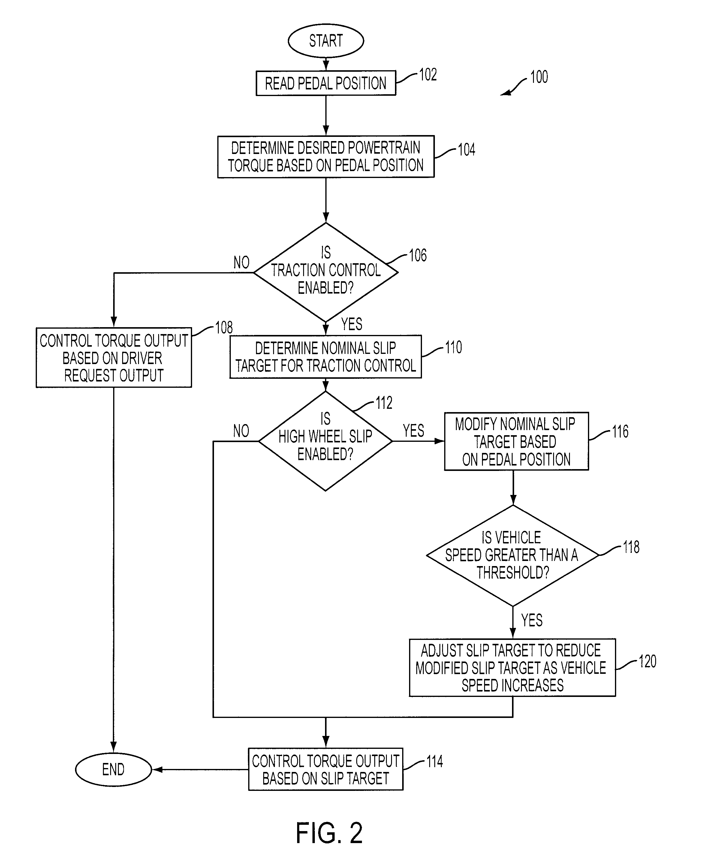
[0006]The systems and methods described above allow the driver to modify the wheel slip in a controlled way during specific traction control conditions. Thus, the driver is given some degree of control over vehicle operation during some traction events, such as when a vehicle becomes stuck. In this way, the driver may be satisfied that all means were attempted to move the vehicle. Further, the high wheel slip may assist to move the stuck vehicle under some conditions. Moreover, since the duration for the stuck vehicle condition and the vehicle speed are accounted for by the slip variation, the different operations, such as normal vehicle operation, normal traction control and traction control with varied slip by the pedal may transition smoothly or continually. Thus, sudden changes in vehicle response may be reduced.

Problems solved by technology

Traction control for a non-moving (stuck) vehicle may be challenging due to potential customer dissatisfaction.
Stuck vehicle conditions may occur when traveling up an icy drive-way, parking and / or sinking in a soft surface rut where the vehicle's driven wheels loose traction to the road surface and simply spin without moving the vehicle.
The reduced wheel spin increases the traction between the wheels and road surface, which may result in the vehicle's moving.
However, such traction control may not always be successful in moving the vehicle.
Further, lack of control on a vehicle operation during the traction control may result in customer dissatisfaction.
For example, under some conditions, no matter how much a driver presses an accelerator pedal, changes in vehicle operations (e.g., tire whine or engine operation) cannot be noticed by the driver.
Further, in some conditions, the driver may find that extra slip or changing slip achieved when the vehicle is back in a normal operation mode would actually help dig out or otherwise free the vehicle, which may further frustrate the driver due to lack of control in traction control mode.

Method used


Image

  • Stuck vehicle with time and pedal related traction control
  • Stuck vehicle with time and pedal related traction control
  • Stuck vehicle with time and pedal related traction control

Examples


Embodiment Construction

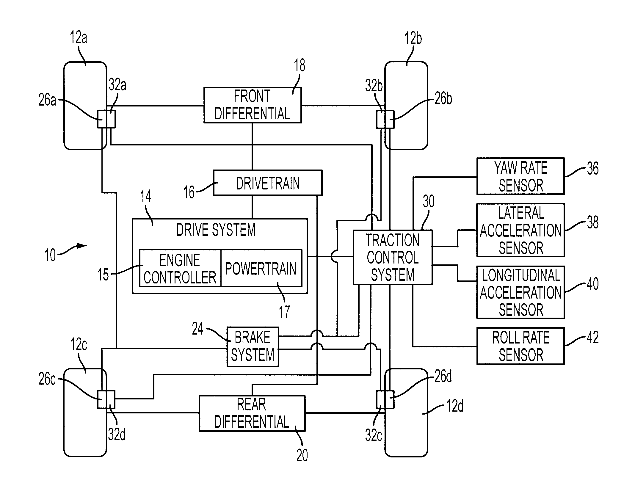
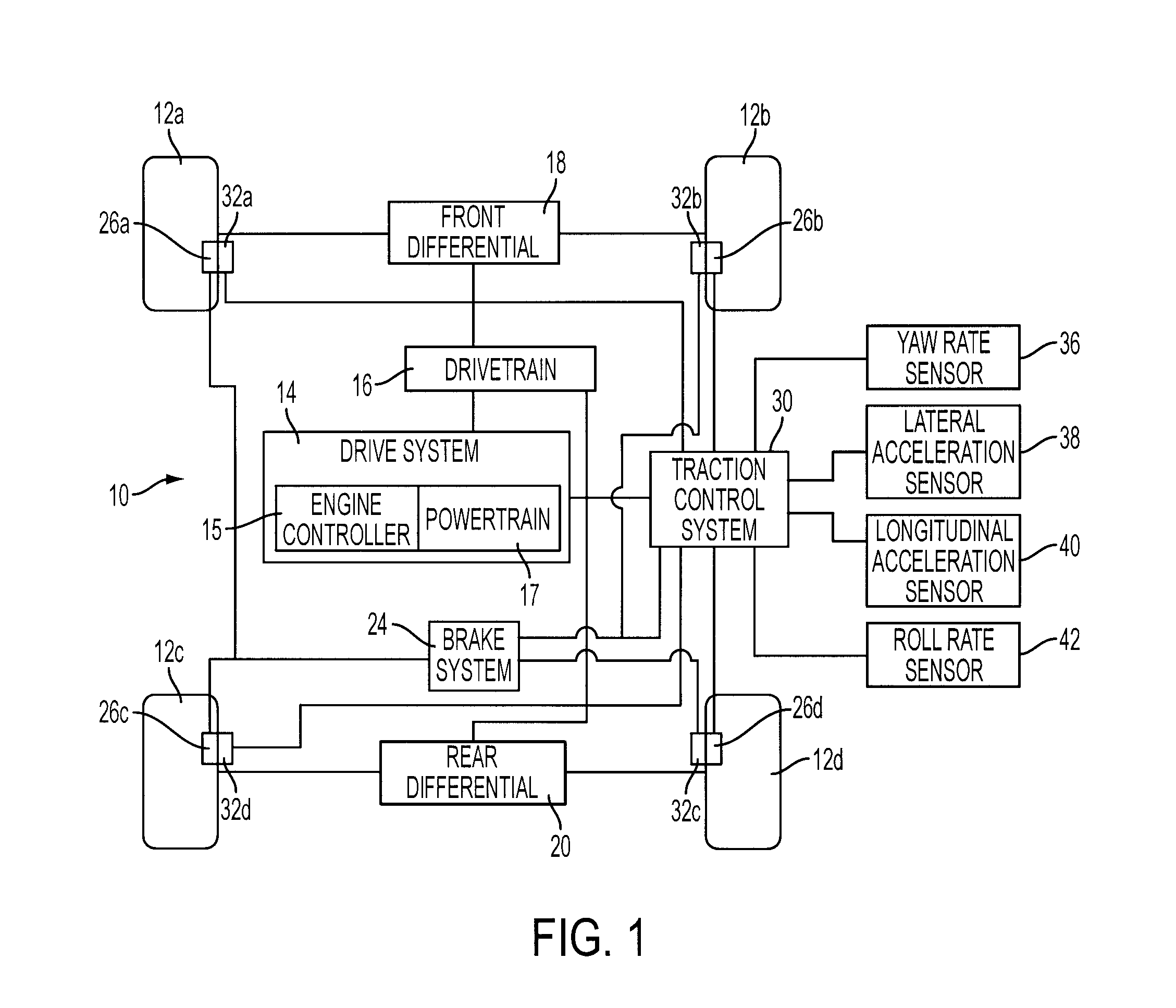
[0016]FIG. 1 is a block diagram of a vehicle 10 having a traction control system. As shown in FIG. 1, vehicle 10 may comprise wheel and tire assemblies 12a, 12b, 12c, and 12d. A drive system 14 coupled to a drivetrain 16 may provide power to the wheel and tire assemblies 12a-d through a front differential 18 and rear differential 20. Drive system 14 may include an engine controller 15 and a powertrain 17. Engine controller 15 may be a microprocessor-based system. Powertrain 17 may provide power by a power generating unit, such as an internal combustion engine, a hybrid electric system, an electric drive system, or a fuel cell system. Engine controller 15 may control the amount of torque and thus the amount of slip generated at each of the wheels. Drive system 14 may vary the amount of power output to effect a change in torque at wheel and tire assemblies 12a-d.

[0017]Drive system 14 may provide torque through drivetrain 16, which may include a transmission, front differential 18 and...


PUM


Abstract

A method for controlling a powertrain of a vehicle is provided for traction control. The method comprises controlling wheel slip to a first amount, the first amount independent of a driver requested output; and controlling the wheel slip to a second amount when a vehicle speed is less than a threshold for a first duration, the second amount based on the driver requested output. In this way, the driver is allowed to modify the wheel slip in a controlled way during specific traction control conditions.

Description

FIELD OF INVENTION[0001]The present application relates to traction control of a vehicle.BACKGROUND[0002]Traction control for a non-moving (stuck) vehicle may be challenging due to potential customer dissatisfaction. Stuck vehicle conditions may occur when traveling up an icy drive-way, parking and / or sinking in a soft surface rut where the vehicle's driven wheels loose traction to the road surface and simply spin without moving the vehicle. When a stuck vehicle condition is sensed by a vehicle controller, traction control may be activated. Typically, traction control overrides a driver's torque request and instead operates the engine at a reduced torque output to reduce the wheel spin by decreasing the engine torque and / or increasing wheel braking. The reduced wheel spin increases the traction between the wheels and road surface, which may result in the vehicle's moving.[0003]However, such traction control may not always be successful in moving the vehicle. Further, lack of control...

Claims


Application Information

Patent Timeline
Patent Type & Authority Patents(United States)
IPC IPC(8): B60K28/16
CPCB60K28/16B60T8/175B60W2520/105B60W2520/125B60W2520/14B60W2520/18B60W2530/20B60W2550/148B60W2552/40B60W10/04B60W10/18B60W30/18172
Inventor LUEHRSEN, ERICFODOR, MICHAEL GLENNPERLICK, DONDUNN, DANIEL
Owner FORD GLOBAL TECH LLC
Learn More