Process for separating carbon dioxide from flue gas using sweep-based membrane separation and absorption steps

a technology of membrane separation and carbon dioxide, applied in separation processes, emission prevention, lighting and heating apparatus, etc., can solve the problems of power plants producing enormous amounts of flue gas, and achieve the effect of reducing the amount of co2

Active Publication Date: 2012-08-21
MEMBRANE TECH & RES
View PDF21 Cites 22 Cited by
  • Summary
  • Abstract
  • Description
  • Claims
  • Application Information

AI Technical Summary

Benefits of technology

[0015]The process of the invention involves treating the exhaust or flue gas to remove carbon dioxide. In preferred embodiments, the carbon dioxide level of the exhaust gas is reduced to as low as 5 vol % or less, and most preferably to 3 vol % or less. Discharge of such a stream to the environment is much less damaging than discharge of the untreated exhaust.
[0036]Another objective of the invention is to minimize the amount of CO2 in the vent stream, which is often released directly to the environment. As such, the vent stream preferably comprises less than 5 vol % CO2; more preferably, less than 4 vol % CO2; and, most preferably, less than 3 vol % CO2.

Problems solved by technology

In particular, power plants generate enormous amounts of flue gas.

Method used


Image

  • Process for separating carbon dioxide from flue gas using sweep-based membrane separation and absorption steps
  • Process for separating carbon dioxide from flue gas using sweep-based membrane separation and absorption steps
  • Process for separating carbon dioxide from flue gas using sweep-based membrane separation and absorption steps

Examples


example 1

Bases of Calculations for Other Examples

[0091](a) Membrane permeation experiments: The following calculations were performed using a composite membrane having a polyether-based selective layer with the properties shown in Table 1.

[0092]

TABLE 1GasPermeance (gpu)*CO2 / Gas SelectivityCarbon dioxide1,000  —Nitrogen3033Oxygen6017Hydrogen100 10Water5,000** —*Gas permeation unit; 1 gpu = 1 × 10⁻⁶ cm3 (STP) / cm2 · s · cmHg**Estimated, not measured

[0093](b) Calculation methodology: All calculations were performed using a modeling program, ChemCad 5.6 (ChemStations, Inc., Houston, Tex.), containing code for the membrane operation developed by MTR's engineering group. For the calculations, all compressors and vacuum pumps were assumed to be 75% efficient. In each case, the modeling calculation was performed to achieve about 80-90% recovery of carbon dioxide from the flue gas stream.

[0094]To facilitate operation of the calculation software, for Examples 1 through 3, the base case air flow provide...

example 2

Serial Carbon Dioxide Capture / Membrane Sweep (not in Accordance with the Invention)

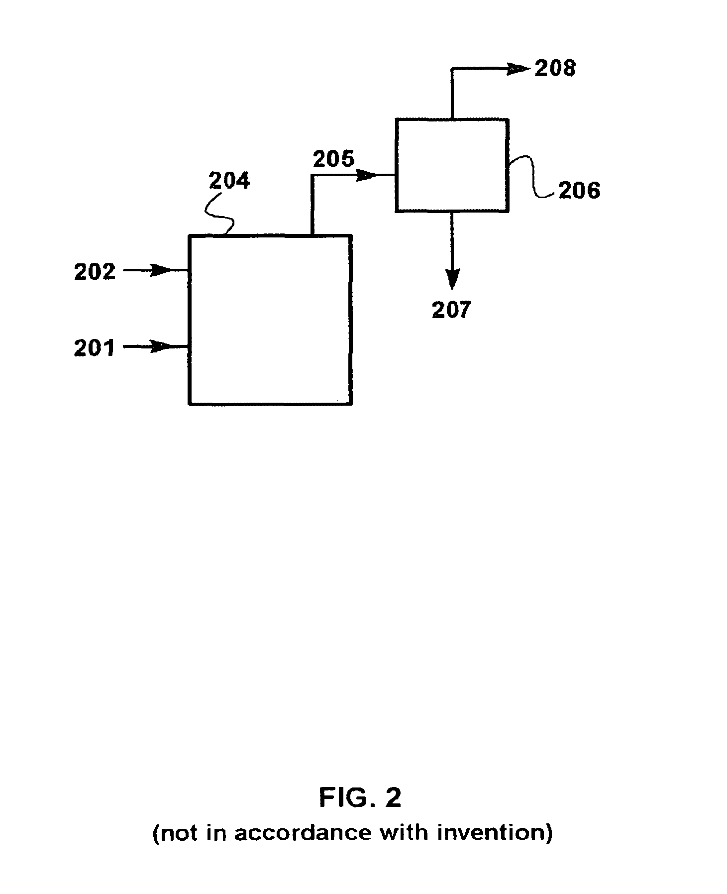
[0100]A computer calculation was performed to determine the chemical composition of exhaust gas from a coal combustion process, where an amine-based carbon dioxide capture step and the membrane-based separation step are performed serially. FIG. 3 is a schematic drawing of a flow scheme for such a serial combustion process.

[0101]Referring to FIG. 3, coal 303 and air stream 304 are introduced into combustion step or zone 312. Stream 304 is made up of recycled exhaust stream 302 and additional air or oxygen supply stream 315.

[0102]Combustion exhaust stream 305 is withdrawn, then routed through a condenser (not shown), where water is knocked out of the stream. The dehydrated exhaust stream 305 is then routed to an amine scrubbing plant 314, where carbon dioxide-rich stream 307 is withdrawn, and carbon dioxide-depleted stream 306 is routed to a sweep-based membrane separation step. The membrane separation ...

example 3

Process of the Invention

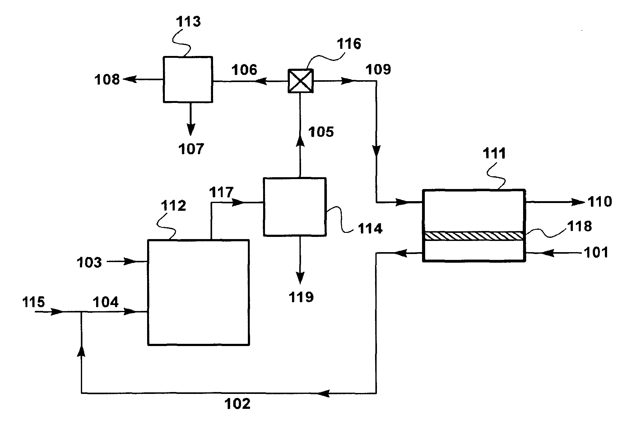
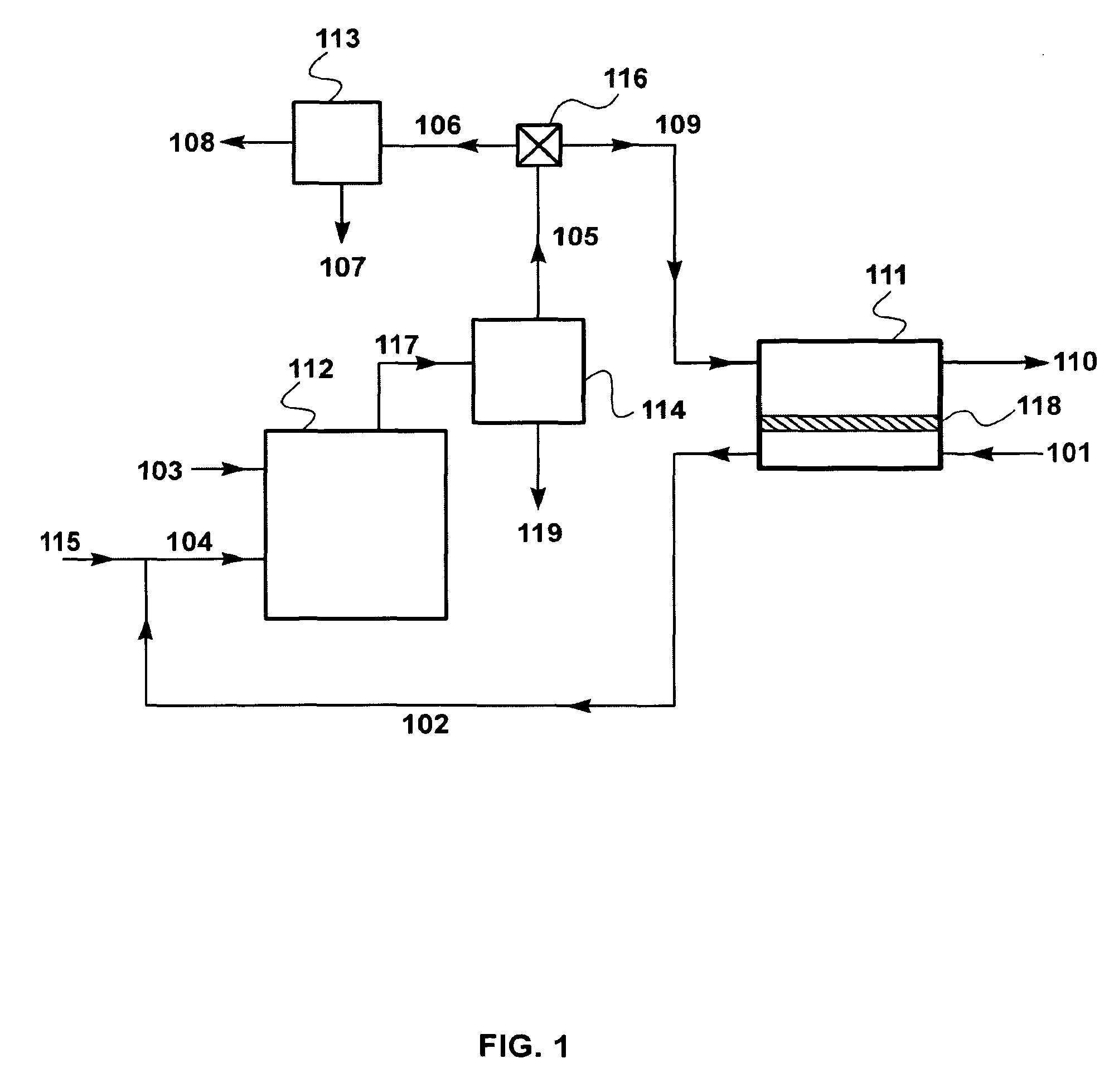
[0106]The calculations for this Example were performed using the flow scheme shown in FIG. 1 and described in the Detailed Description, above. This flow scheme includes an amine scrubbing step 113 performed in parallel with a sweep-based membrane separation step 111.

[0107]In this set of calculations, the membrane area was assumed to be 700 m2, and the combustion exhaust stream split was set at 1:1 (flow to carbon dioxide capture step:flow to sweep-based membrane separation step). Air flow 101 is 900 kg / h. The results of this calculation are shown in Table 4.

[0108]

TABLE 4StreamAmineCO2Vent GasMembrane ResidueGas toPlantConcentrateFrom AmineMembraneTreated FlueAirCombustorCoalFeedStreamUnitFeedGas(101)(102)(103)(106)(107)(108)(109)(110)ParameterTotal Flow (kg / h)9001,07355561180372561378Temperature (° C.)2528253030253025Pressure (bar)1.01.01.01.01.01.01.01.0Component (vol %)Coal0010000000Oxygen21.016.502.302.12.37.4Nitrogen79.070.1070.70.192.070.791.8Carbon Diox...


PUM

PropertyMeasurementUnit
vol %aaaaaaaaaa
vol %aaaaaaaaaa
vol %aaaaaaaaaa

Abstract

A gas separation process for treating flue gases from combustion processes, and combustion processes including such gas separation. The invention involves routing a first portion of the flue gas stream to be treated to an absorption-based carbon dioxide capture step, while simultaneously flowing a second portion of the flue gas across the feed side of a membrane, flowing a sweep gas stream, usually air, across the permeate side, then passing the permeate / sweep gas to the combustor.

Description

[0001]This invention was made in part with U.S. Government support under SBIR Award No. DE-NT-000-5312, awarded by the U.S. Department of Energy. The U.S. Government has certain rights in this invention.[0002]The present application claims priority to PCT Application Serial No. PCT / US2010 / 002481, filed Sep. 13, 2010.FIELD OF THE INVENTION[0003]The invention relates to membrane-based gas separation processes, and specifically to processes using a sweep gas on the permeate side of the membranes to remove carbon dioxide from flue gas. In particular, the invention concerns the use of sweep-based membrane separation in conjunction with absorption to capture carbon dioxide.BACKGROUND OF THE INVENTION[0004]Many combustion processes produce flue gases contaminated with carbon dioxide that contribute to global warming and environmental damage.[0005]Such gas streams are difficult to treat in ways that are both technically and economically practical, and there remains a need for better treatme...

Claims


Application Information

Patent Timeline
Patent Type & Authority Patents(United States)
IPC IPC(8): B01D53/22C01B32/50
CPCB01D53/229B01D53/62B01D53/78F23J15/006F23J15/02F23L7/007B01D2256/22B01D2257/504F23J2215/50Y02C10/04Y02C10/10Y02E20/344Y02E20/32Y02E20/34Y02C20/40
Inventor WIJMANS, JOHANNES G.BAKER, RICHARD W.MERKEL, TIMOTHY C.
Owner MEMBRANE TECH & RES
Why Eureka
Try Eureka