Ultra-high multiplex analytical systems and methods

a technology of multiplex analysis and high multiplex, applied in the field of ultra-high multiplex analysis systems and methods, can solve the problems of reducing the signal to noise ratio resulting from either or both of lower signals, and increasing the difficulty of multiplex analysis

Active Publication Date: 2012-08-21
PACIFIC BIOSCIENCES
View PDF25 Cites 68 Cited by
  • Summary
  • Abstract
  • Description
  • Claims
  • Application Information

AI Technical Summary

Problems solved by technology

In optical analyses, increasing multiplex often poses increased difficulties, as it may require more complex optical systems, increased illumination or detection capabilities, and new reaction containment strategies.
In some cases, systems seek to increase multiplex by many fold, and even orders of magnitude, which further implicate these considerations.
Likewise, in certain cases, the analytical environment for which the systems are to be used is so highly sensitive that variations among different analyses in a given system may not be tolerable.
These goals are often at odds with a brute force approach of simply making systems bigger and of higher power, as such steps often give rise to even greater consequences, e.g., in inter reaction cross-talk, decreased signal to noise ratios resulting from either or both of lower signal and higher noise, and the like.

Method used


Image

  • Ultra-high multiplex analytical systems and methods
  • Ultra-high multiplex analytical systems and methods
  • Ultra-high multiplex analytical systems and methods

Examples


example 1

Parabolic Mirror Substrates

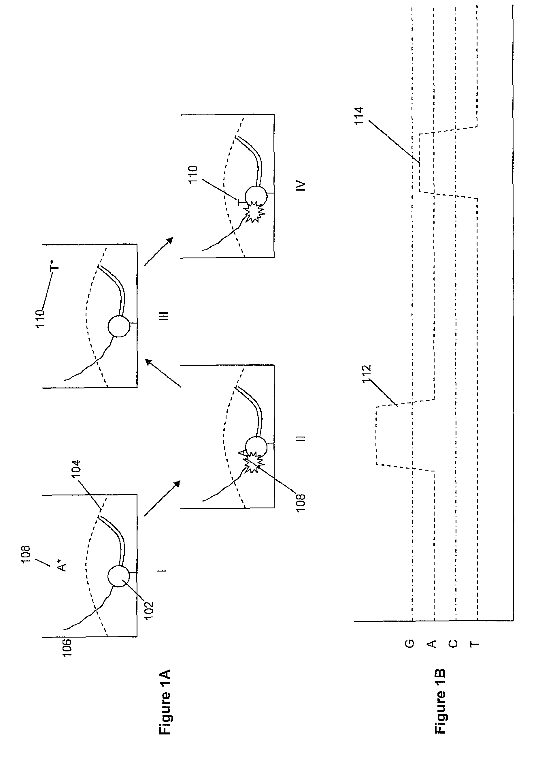
[0206]Substrates were fabricated having zero mode waveguides disposed through a metal layer that was deposited over a parabolic feature defined in a glass substrate. The devices were fabricated according to the process set out in FIG. 10 and the accompanying description, except that subsequent planarization of the substrate was not carried out (steps V-VII). The aperture through the metal layer which defines the core of the zero mode waveguide was fabricated using a focused ion beam (FIB etch process) to define a core of approximately 120 nm in diameter. The resulting structure is shown in FIG. 31A, under scanning electron microscopy (SEM), imaged from the metal layer side of the structure. The core of the zero mode waveguide is visible as the opening in the center top of the structure.

[0207]A comparison substrate was also provided having a zero mode waveguide of approximately the same cross sectional dimensions disposed in a planar metal layer over a plan...

example 2

Theoretical Modeling of Conical Mirror Substrates

[0208]Structures were modeled using the various components illustrated in FIGS. 32 and 33, respectively. For example, with respect to the straight conical structure illustrated in FIG. 32, dimensions were set as follows: d1=1.25 μm; d2=5 μm and h=4.69 μm. The model assumed that an objective lens used to collect emitted light from the substrate / reflector component has a numerical aperture of 0.5 with a highest collection angle of + / −20 degrees with respect to the optical axis, thereby providing a collection angle with respect to the bottom surface of the substrate of from 70 to 110 degrees. Based upon the conical model shown in FIG. 32, the ray angle that is reflected out of the cone is from 43.58 (Θtr) to 105.52 (Θbr) degrees.

[0209]For the two staged conical reflector shown in FIG. 33, the dimensions were set to: d1=1.25 μm; d2=3 μm; d3=5 μm; h1=1 μm; and h2=3.69 μm. In this case, the ray angle that is reflected and comes out of the r...

example 3

Production of Array of Nanoscale Reaction Regions on Micromirror Structures Using Sacrificial Pillars

[0211]Polygermanium was deposited onto fused silica as a 500 nm layer by LPCVD at 350° C. Pillars were etched into a polygermanium using a 248 nm stepper, Lam etcher, width tuning from 300 nm to 120-150 nm. Mirrors were etched using a 248 nm stepper and Centura-MXP etcher. The array was then annealed at 600° C. to reduce autofluorescence and outgass the organic contaminants, followed by evaporation of aluminum and de-capping (removal of the polygermanium) in wet solution (30% H202 at 50° C.) without attacking aluminum on mirror facets. FIG. 34 shows an SEM micrograph showing a portion of the array of reaction regions with associated micromirrors. FIG. 35 shows a single micromirror structure having a reaction region on its top. FIG. 36 shows a nanoscale reaction region on the top of a micromirror structure.


PUM

PropertyMeasurementUnit
diametersaaaaaaaaaa
diametersaaaaaaaaaa
diametersaaaaaaaaaa

Abstract

Apparatus, systems and methods for use in analyzing discrete reactions at ultra high multiplex with reduced optical noise, and increased system flexibility. Apparatus include substrates having integrated optical components that increase multiplex capability by one or more of increasing density of reaction regions, improving transmission of light to or collection of light from discrete reactions regions. Integrated optical components include reflective optical elements which re-direct illumination light and light emitted from the discrete regions to more efficiently collect emitted light. Particularly preferred applications include single molecule reaction analysis, such as polymerase mediated template dependent nucleic acid synthesis and sequence determination.

Description

CROSS-REFERENCE TO RELATED APPLICATIONS[0001]The present application claims priority from Provisional U.S. Patent Application No. 61 / 101,555, filed Sep. 30, 2008 and Provisional U.S. Patent Application No. 61 / 223,628 filed Jul. 7, 2009, the full disclosures of which are hereby incorporated by reference in their entirety for all purposes.STATEMENT REGARDING FEDERALLY SPONSORED RESEARCH[0002]Not Applicable.BACKGROUND OF THE INVENTION[0003]In analytical systems, the ability to increase the number of analyses being carried out at any given time by a given system has been a key component to increasing the utility and extending the lifespan of such systems. In particular, by increasing the multiplex factor of analyses with a given system, one can increase the overall throughput of the system, thereby increasing its usefulness while decreasing the costs associated with that use.[0004]In optical analyses, increasing multiplex often poses increased difficulties, as it may require more comple...

Claims


Application Information

Patent Timeline
Patent Type & Authority Patents(United States)
IPC IPC(8): C12M1/36G01N21/00G01J3/00
CPCG01N21/253G01N21/6452G02B6/131G02B6/136G02B6/132G02B6/12002C23C16/50B05D1/005G02B2006/12164G02B2006/12104G02B2006/12035G02B2006/12197G02B2006/12061
Inventor ZACCARIN, DENISLUNDQUIST, PAULZHAO, PEIQIANZHONG, CHENG FRANKTURNER, STEPHENHUANG, YANQIAOMONADGEMI, PEZHMANSAXENA, RAVIGROT, ANNETTERULISON, AARON
Owner PACIFIC BIOSCIENCES
Why Eureka
Try Eureka