Manufacturing method of hermetic container

a technology of hermetic container and manufacturing method, which is applied in the manufacture of electrode systems, mechanical control devices, instruments, etc., can solve the problems of defective junction, air tightness deterioration, and glass substrate that is not easy to deform toward the sealing material, so as to reduce the spacing distance between the first and second glass substrates at the coupling portion, the effect of high reliability

Inactive Publication Date: 2012-09-04
CANON KK
View PDF37 Cites 7 Cited by
  • Summary
  • Abstract
  • Description
  • Claims
  • Application Information

AI Technical Summary

Benefits of technology

[0013]When the scanning is performed to the first straight line portion and the coupling portion of the sealing material while irradiating the local heating light at least once, the sealing material is softened, and the film thickness decreases. However, in the assembling step, the coupling portion is formed to have the film thickness thinner than that of or to have the density lower than that of the region adjacent to the coupling portion of the first straight line portion. For this reason, as compared with a case where the coupling portion is formed with the film thickness or the film density approximately the same as that of the region adjacent to the coupling portion of the first straight line portion, the spacing distance between the first and second glass substrates at the coupling portion can be shortened. Consequently, the above-described inconsistency and the defective junction due to the relevant inconsistency are less-likely to occur, whereby both joining strength and airtightness can be achieved.
[0014]As just described, according to the present invention, it is possible to provide the manufacturing method of the hermetic container, which achieves both the joining strength and the airtightness and has high reliability.

Problems solved by technology

However, there is a case where airtightness deteriorates due to a defective junction occurring at a coupling portion (corner portion) of the sealing material.
For this reason, since the glass substrate in the coupling portion is sealed or held by these straight line portions, the glass substrate does not easily deform toward the sealing material.
As a result, in the region of the straight line portion adjacent to the coupling portion, since inconsistency occurs between the thickness of the sealing material and the spacing distance between the glass substrates, a defective junction thus occurs.

Method used


Image

  • Manufacturing method of hermetic container
  • Manufacturing method of hermetic container
  • Manufacturing method of hermetic container

Examples


example 1

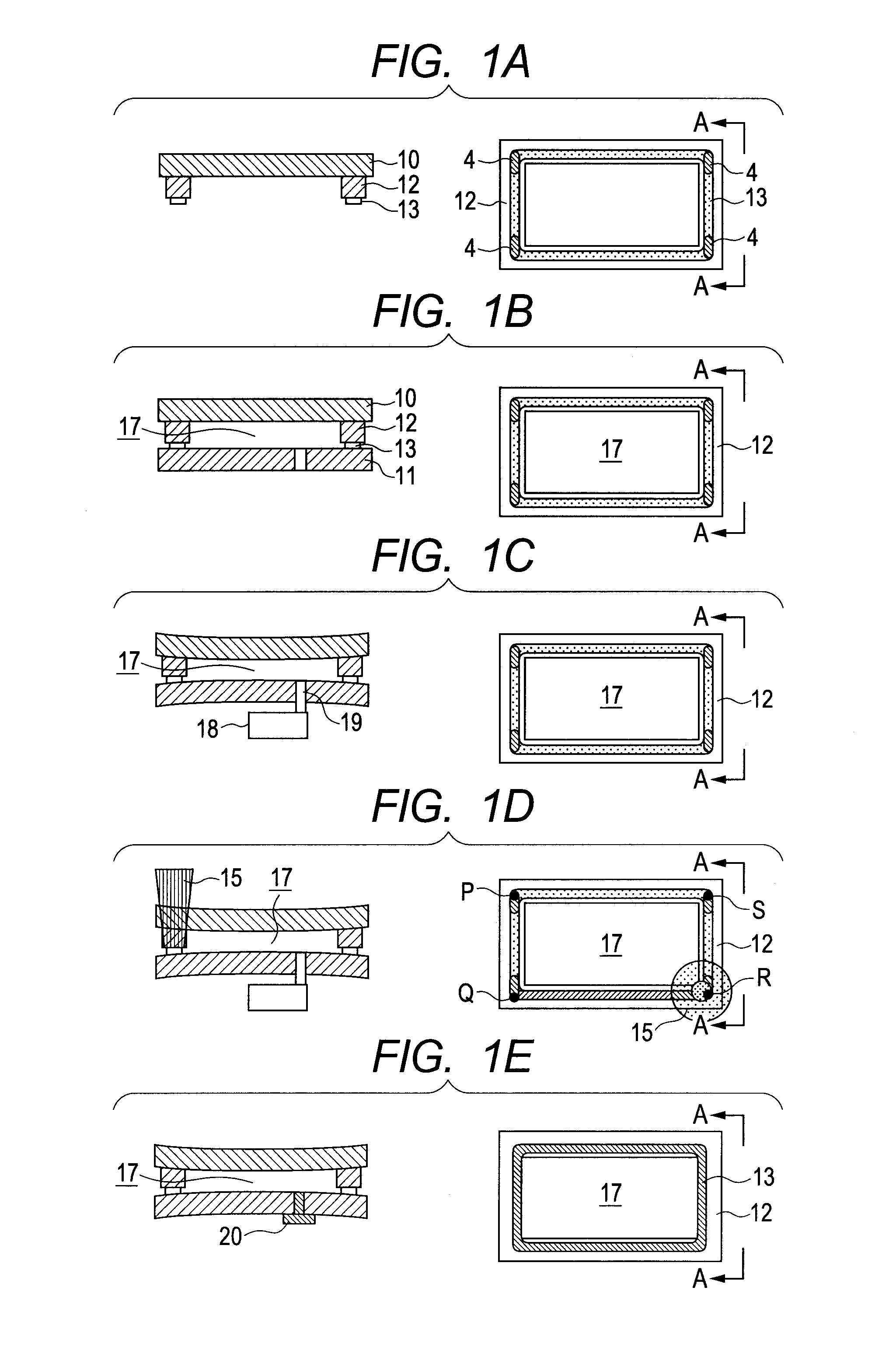
[0062]By applying the above-described embodiments, an integrated matter of a frame member and a face plate is airtightly sealed with a rear plate, further, after the pressurization is released, an internal space is again evacuated from an exhaust hole and the exhaust hole is sealed by a cover member, thereby manufacturing a vacuum hermetic container which can be applied to an FED (Field Emission Display).

[0063](Step 1)

[0064]First, a face plate 10 is formed. More specifically, a high strain point glass substrate having a thickness of 1.8 mm (PD200: made by Asahi Glass Co., Ltd.) is formed into a plate glass having an external shape of 980 mm×570 mm×1.8 mm by performing a cutting work to prepare it as a plate glass shaped face plate 10 having that external shape. Subsequently, a surface of the face plate 10 is degreased by an organic solvent cleaning, a pure water rinsing and a UV-ozone cleaning. Then, by forming phosphor, a black matrix, and an anode (not illustrated) as a pattern on...

example 2

[0077]In this example, as indicated in FIGS. 4A to 4E, the low film-thickness region 4 is formed on only the coupling portion 3 instead of the low film-thickness region 4 in the example 1 as illustrated in FIG. 4A. Excepting this point, the hermetic container which can be applied to the FED apparatus is manufactured based on the conditions similar to those of the example 1. The film thickness of the sealing material 13 is set to become 8.0 μm at the general portion and 7.0 μm at coupling portions. The film thickness of the sealing material after completing the hermetic container was 6.4 μm.

[0078]When the completed FED apparatus is made to be operated, it was confirmed that the stable electron emission and image display for a long time can be performed and the stable airtightness at a level capable of applying to the FED apparatus is ensured.


PUM

PropertyMeasurementUnit
thicknessaaaaaaaaaa
thicknessaaaaaaaaaa
thicknessaaaaaaaaaa

Abstract

A manufacturing method of a high-reliability hermetic container includes an assembling step of arranging, between first and second glass substrates, a sealing material including first and second straight line portions stretching in different directions and a coupling portion connecting these straight line portions, with a viscosity of the sealing material having a negative temperature coefficient, and a scanning sealing step of performing scanning to the first straight line portion and the coupling portion while irradiating local heating light at least once. Scanning to the second straight line portion and the coupling portion is performed while irradiating the local heating light at least once, and the assembling step further forms at least a part of the sealing material at the coupling portion with a film thickness thinner than the sealing material in a region adjacent to the coupling portion of the first straight line portion.

Description

BACKGROUND OF THE INVENTION[0001]1. Field of the Invention[0002]The present invention relates to a manufacturing method of a hermetic container and, more particularly, to a manufacturing method of a hermetic container for an image display apparatus having electron-emitting devices in each of which an inside is held in a vacuum state and a phosphor film.[0003]2. Description of the Related Art[0004]Image display apparatuses of a flat panel type such as an organic LED display (OLED), a field emission display (FED), a plasma display panel (PDP), and the like are well known. Each of those image display apparatuses is equipped with a container which is manufactured by airtightly sealing glass substrates facing each other and of which an internal space is partitioned to an external space. To manufacture such a hermetic container, a spacing distance defining member, a local adhesive, and the like are arranged between the facing glass substrates as necessary, a sealing material is arranged i...

Claims


Application Information

Patent Timeline
Patent Type & Authority Patents(United States)
IPC IPC(8): H01J9/00
CPCC03C23/0025C03C27/10H01J9/261H01L51/5246H10K50/8426C03C27/06H01J9/26B65D13/02
Inventor ITO, NOBUHIROMATSUMOTO, MAMO
Owner CANON KK
Why Eureka
Try Eureka