
Contact for coaxiable cable having a tearable band between a conductor barrel and a crimp barrel

a coaxial cable and contact technology, applied in the direction of line/current collector details, connection formation by deformation, electrical equipment, etc., can solve the problems of affecting the impedance fluctuation, the fixing strength between the outer conductor contact and the coaxial cable is reduced, and the relative drop of the coaxial cable is affected, so as to reduce the production cost of the wiring harness, reduce the end processing step (processing time) of the coaxial cable, and increase the reliability and accuracy of the attachmen

Inactive Publication Date: 2012-10-02
JST MFG CO LTD
View PDF16 Cites 11 Cited by
  • Summary
  • Abstract
  • Description
  • Claims
  • Application Information

AI Technical Summary

Benefits of technology

This configuration enhances attachment accuracy and reliability, reduces end processing time, and stabilizes Voltage Standing Wave Ratio (VSWR), thereby improving signal transmission and lowering production costs.

Problems solved by technology

If a crimping force is high in a case of crimping the outer conductor by the conductor barrel, the conductor is deformed to be squashed and this affects impedance fluctuation during transmission of an electronic signal.
On the other hand, if a crimping force is low in a case of crimping the outer conductor by the conductor barrel, fixing strength between the outer conductor contact and the coaxial cable lowers and this may cause relative drop-off when a tensile force in a direction of separating the outer conductor contact and the coaxial cable is applied.
As a result, it is difficult to reduce production cost of a so-called wiring harness, in which connectors for coaxial cable are attached to ends of a coaxial cable.
As a result, as in the first embodiment, it is difficult to reduce production cost of a so-called wiring harness, in which connectors for coaxial cable are attached to ends of a coaxial cable.
If the VSWR is high, transmission failure such as noise may be caused on a reception side.

Method used


Image

  • Contact for coaxiable cable having a tearable band between a conductor barrel and a crimp barrel
  • Contact for coaxiable cable having a tearable band between a conductor barrel and a crimp barrel
  • Contact for coaxiable cable having a tearable band between a conductor barrel and a crimp barrel

Examples


Embodiment Construction

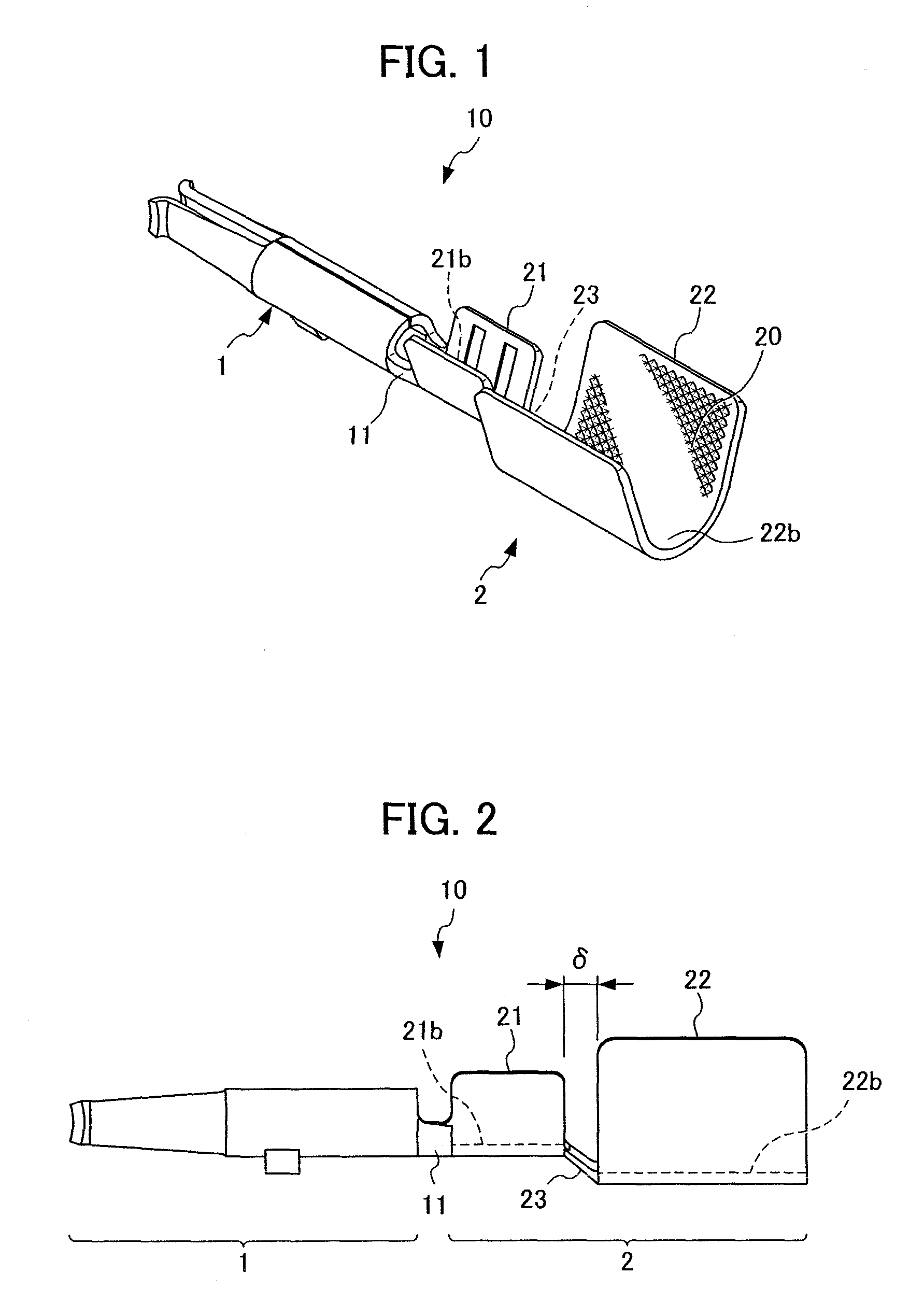
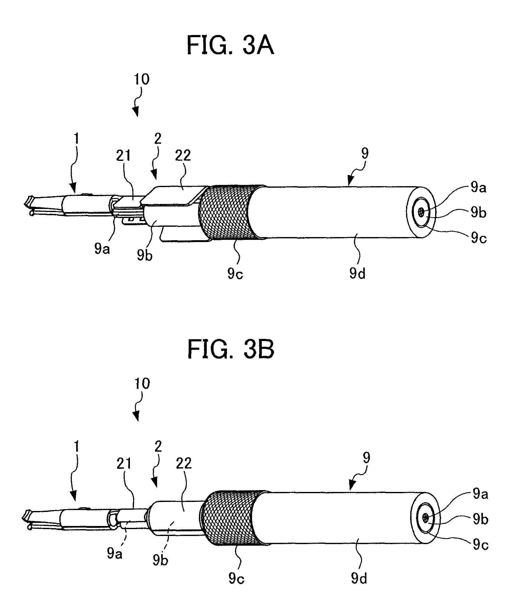
[0032]In the present invention, the inner conductor contact for crimping the inner conductor of a coaxial cable and the open crimp barrel for crimping the dielectric body of the coaxial cable are integrally configured. When the open crimp barrel is crimped to the dielectric body of the coaxial cable, the sleeve that has been crimped is separated from the inner conductor contact such that the sleeve in a state of being covered with the braided wire functions as a sleeve for protecting the dielectric body when a braided wire is crimped. Such a configuration can solve the abovementioned problem. A preferred mode for carrying out the present invention is described hereinafter with reference to drawings.

Configuration of Contact for Coaxial Cable

[0033]First, a configuration of a contact for coaxial cable according to an embodiment of the present invention is described. FIG. 1 is a perspective view showing a configuration of a contact for coaxial cable according to an embodiment of the pre...


PUM

PropertyMeasurementUnit
frequencyaaaaaaaaaa
dielectricaaaaaaaaaa
cylindrical shapeaaaaaaaaaa

Abstract

A contact for coaxial cable attached to an end of a coaxial cable includes a contact part and a connection part. The connection part includes a conductor barrel, an open crimp barrel, and a junction band narrow in width. The conductor barrel is disposed on a side to a base end portion of the contact part and can crimp the inner conductor. The open crimp barrel is adjacent to the conductor barrel and can crimp an exposed portion of the dielectric body so as to surround the exposed portion of the dielectric body in a cylindrical shape. The junction band joins the conductor barrel with the open crimp barrel so as to bridge the two. The both end portions of the junction band are torn during or after crimping of the conductor barrel and the open crimp barrel.

Description

[0001]This application is based on and claims the benefit of priority from Japanese Patent Application No. 2010-143093, filed on 23, Jun. 2010 the content of which is incorporated herein by reference.BACKGROUND OF THE INVENTION[0002]1. Field of the Invention[0003]The present invention is related to a contact for coaxial cable and an end processing method for coaxial cable. Particularly, the present invention relates to a structure of a contact for crimping an inner conductor and a dielectric body provided in a coaxial cable, and an end processing method of coaxial cable using the contact.[0004]2. Related Art[0005]A coaxial cable is an unbalanced shielded wire with characteristic impedance being defined for transmitting an electronic signal. The coaxial cable is characterized by preventing electromagnetic wave leakage to the outside and allowing bend to a certain extent, and is used as a feeder cable that connects a TV receiver, a radio or the like with an antenna.[0006]In the coaxia...

Claims


Application Information

Patent Timeline
Patent Type & Authority Patents(United States)
IPC IPC(8): H01R9/05H01R43/04
CPCH01R4/185H01R43/05H01R9/05Y10T29/49192
Inventor KOGA, SHINICHI
Owner JST MFG CO LTD
Learn More