Fiber laser

a fiber laser and fiber technology, applied in the field of fiber lasers, can solve the problems of reducing reducing the efficiency of fiber lasers, and increasing the risk of damage thereon, so as to improve the reliability, prevent efficiency degradation, and improve the reliability of fiber lasers

Inactive Publication Date: 2012-10-02
THE FUJIKURA CABLE WORKS LTD
View PDF20 Cites 52 Cited by
  • Summary
  • Abstract
  • Description
  • Claims
  • Application Information

AI Technical Summary

Benefits of technology

[0034]The fiber laser according to the present invention is provided with a reflection device with a small reflectance. With such a structure, the peak power of the pulse, which is emitted toward a master oscillator (MO) or to the pump light source by self-oscillation or reflection, can be suppressed so as to be taken it down about two places or more.
[0035]In addition, by using a reflection device with a wavelength different from an oscillation wavelength, it is possible to prevent efficiency degradation without causing loss in signal light.
[0036]In addition, since the peak power of the pulse emitted toward the MO or the pump light source by self-oscillation or reflection can be decreased, there is no damage on the pump light source or the MO, and a laser with high reliability can be provided. That is, it is possible to improve the reliability of fiber lasers.
[0037]In addition, depending on the output of the fiber laser, the fiber laser can be manufactured at a low cost since there is no self-oscillation even though there is no PA isolator which has a very high price.

Problems solved by technology

The pulses reach the pump light source or the MO, so that there may be a risk of damage thereon.
In addition, even when the pulses emitted from the MO is entered in a cycle in which the PA does not oscillate by itself and the fiber laser is in a normal operating state, the reflected light from the outside of the PA output may induce oscillation while the pulses are being input.
These pulses reach the pump light source or the MO, so that there may be a risk of damage thereon.
Even if the gain of the rear stage is high, since the ASE light is always coupled thereto, the ASE light is amplified but not to a sufficient level to cause self-oscillation.

Method used


Image

  • Fiber laser
  • Fiber laser
  • Fiber laser

Examples


example

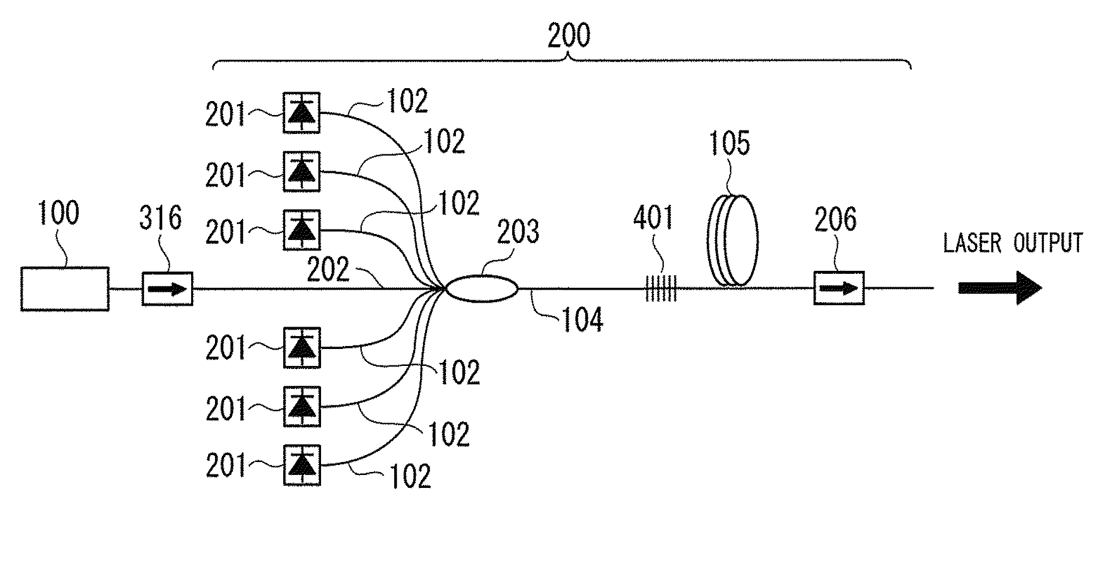
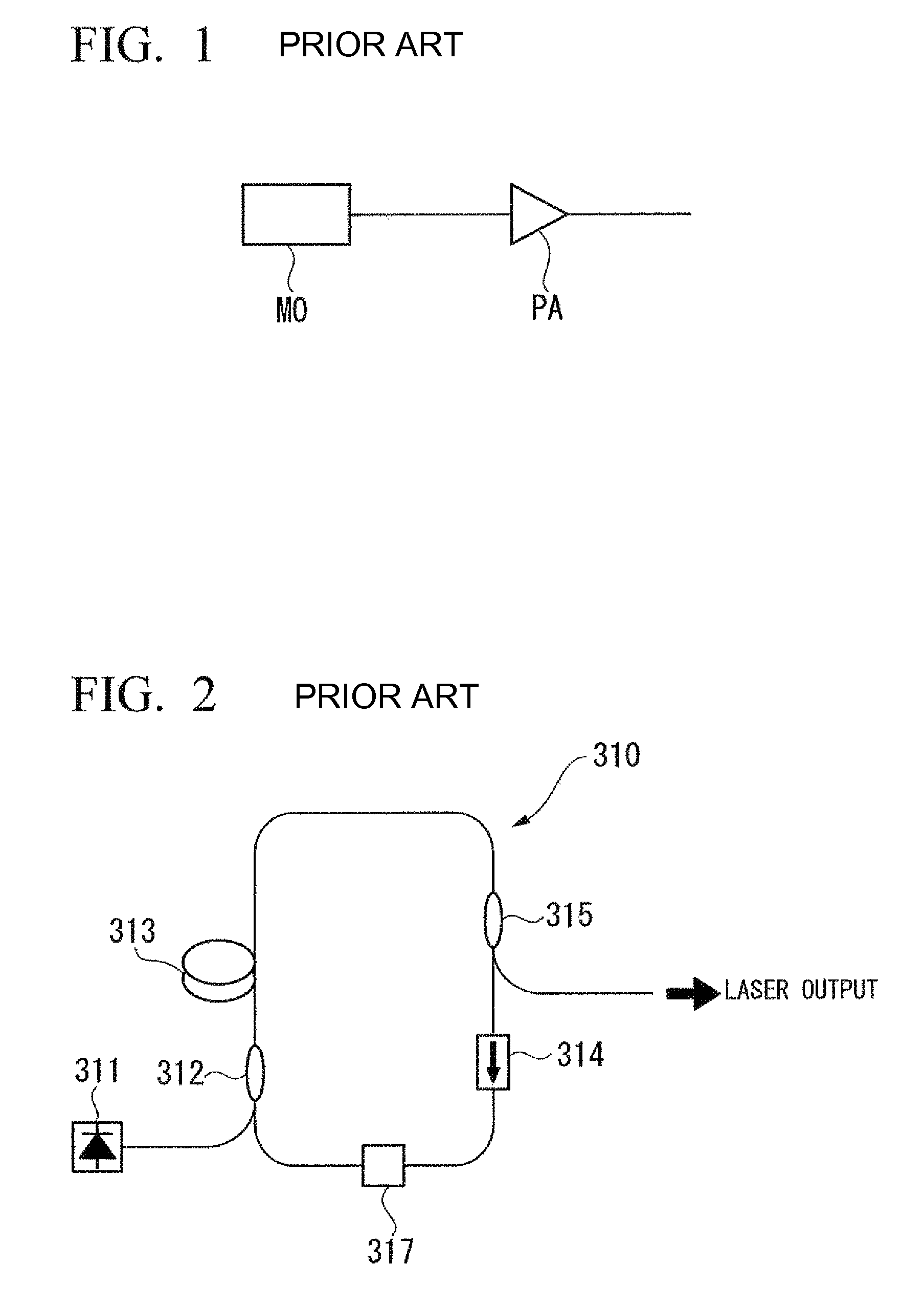
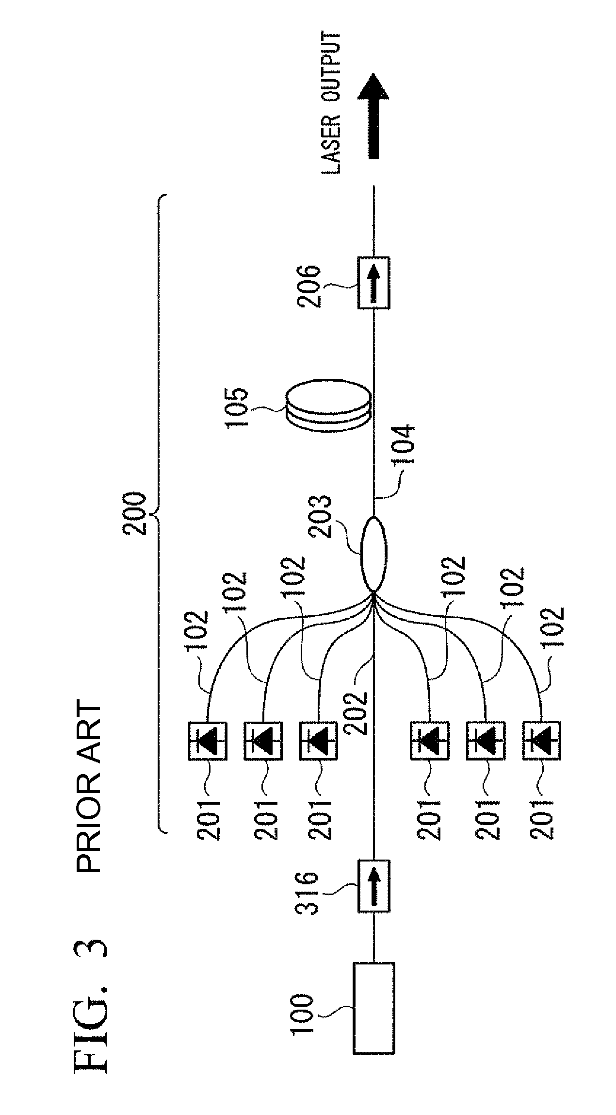
[0071]The known MOPA type fiber laser shown in FIG. 3 (hereinafter, referred to as a comparative example) and the fiber laser shown in FIG. 4 as the embodiment of the present invention were produced by way of experimentation.

[0072]In both the comparative example and the embodiment, a fiber ring laser with an oscillation wavelength of 1064 nm is used as the MO 100.

[0073]As the rare earth-doped double-clad fiber 105, an Yb-doped double-clad fiber is used, of which the diameter of the core is 20 μm, the diameter of a first clad is 400 μm, and the absorption of the core is 1200 dB / m @976 nm.

[0074]As the photocoupler 203, a coupler which has an emission port of which the diameter of the core is 20 μm, and the diameter of the clad is 390 μm is used, in order to reduce the connection loss of the pump light between the photocoupler 203 and the rare earth-doped double-clad fiber 105. Pumping ports are connected to the pump light source. The incident port is composed of six pumping ports 102 ...


PUM


Abstract

A fiber laser of an MOPA type includes an MO which is a laser oscillator for generating seed light, a PA which is a light amplifier connected to a rear stage of the MO, for amplifying and outputting laser light emitted from the MO, and a reflection device which is provided between the MO and the PA. According to the present invention, the MOPA type fiber laser can decrease the peak value of the pulse which is emitted toward the MO or the pump light source by self-oscillation or reflection, and makes it unlikely that the pump light source or the MO will be damaged.

Description

TECHNICAL FIELD[0001]This application is a continuation application based on a PCT Patent Application No. PCT / JP2008 / 058842, filed May 14, 2008, whose priority is claimed on Japanese Patent Application No. 2007-132755 filed May 18, 2007, the entire content of which are hereby incorporated by reference.BACKGROUND ART[0002]In recent years, the output power of fiber lasers continues to increase, and fiber lasers with high output power of more than a kW-order have been developed. Such high power fiber lasers are used in various industrial applications such as processing machines, medical apparatuses, and measuring instruments. The use of fiber lasers have been rapidly widened because in the material-processing field, fiber lasers are superior to other lasers in their light focusing properties and can significantly increase the power density at focusing points, so as to enable precision machining, and because it enables performing a noncontact processing, and also enables processing of h...

Claims


Application Information

Patent Timeline
Patent Type & Authority Patents(United States)
IPC IPC(8): H01S3/30
CPCH01S3/0064H01S3/2308A61B18/22H01S3/06754H01S3/094003H01S3/09415H01S2301/02
Inventor KITABAYASHI, TOMOHARU
Owner THE FUJIKURA CABLE WORKS LTD
Why Eureka
Try Eureka