
Radio frequency built-in self test for quality monitoring of local oscillator and transmitter

Active Publication Date: 2012-10-09
TEXAS INSTR INC
View PDF17 Cites 12 Cited by
  • Summary
  • Abstract
  • Description
  • Claims
  • Application Information

AI Technical Summary

Benefits of technology

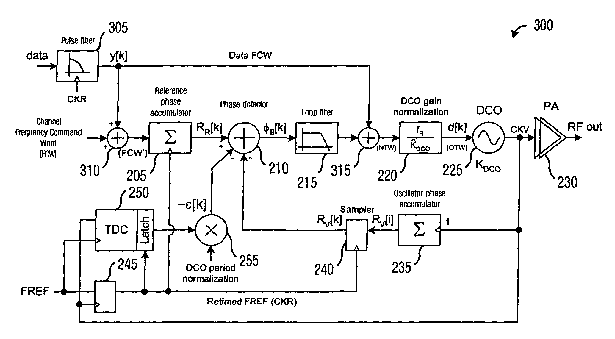
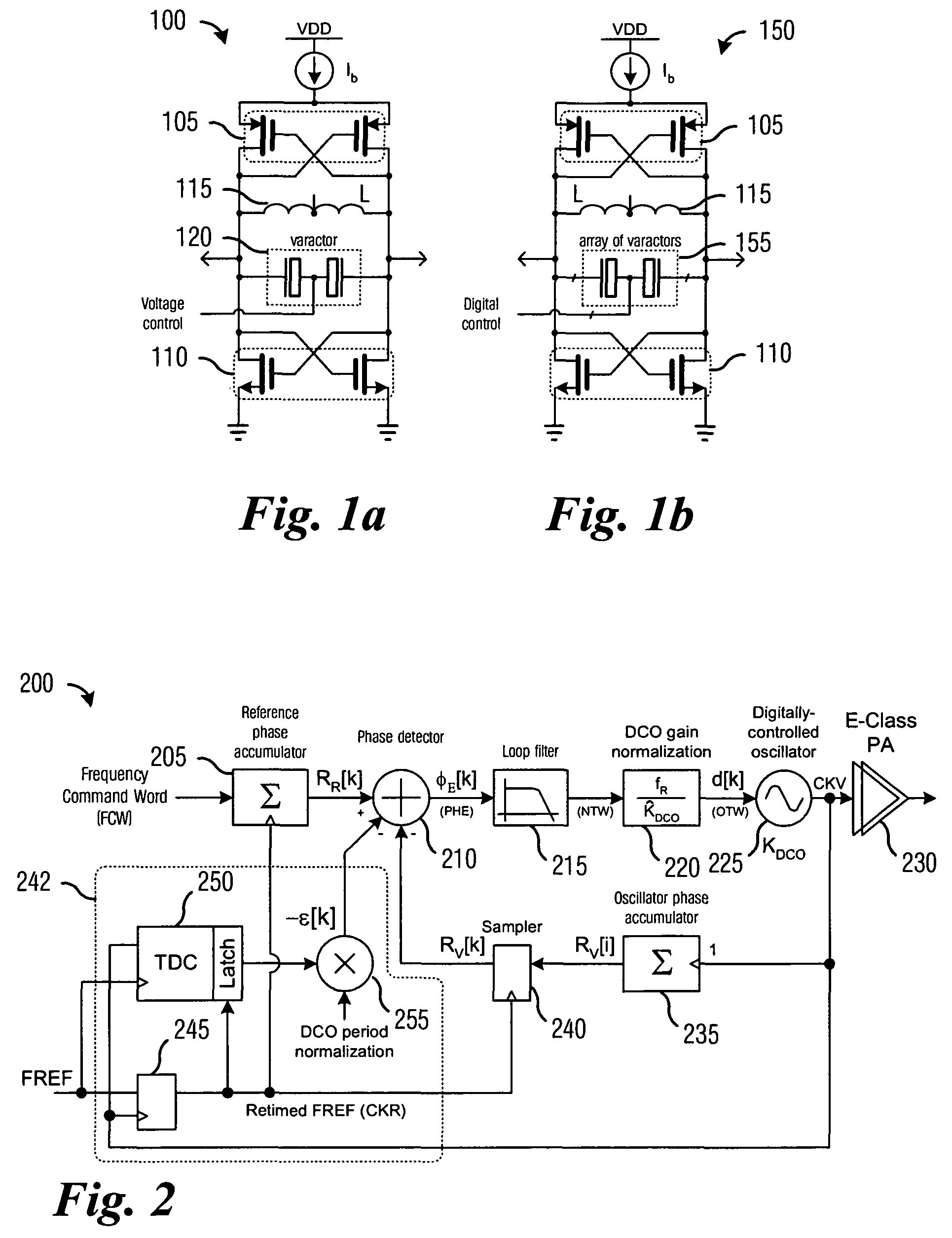
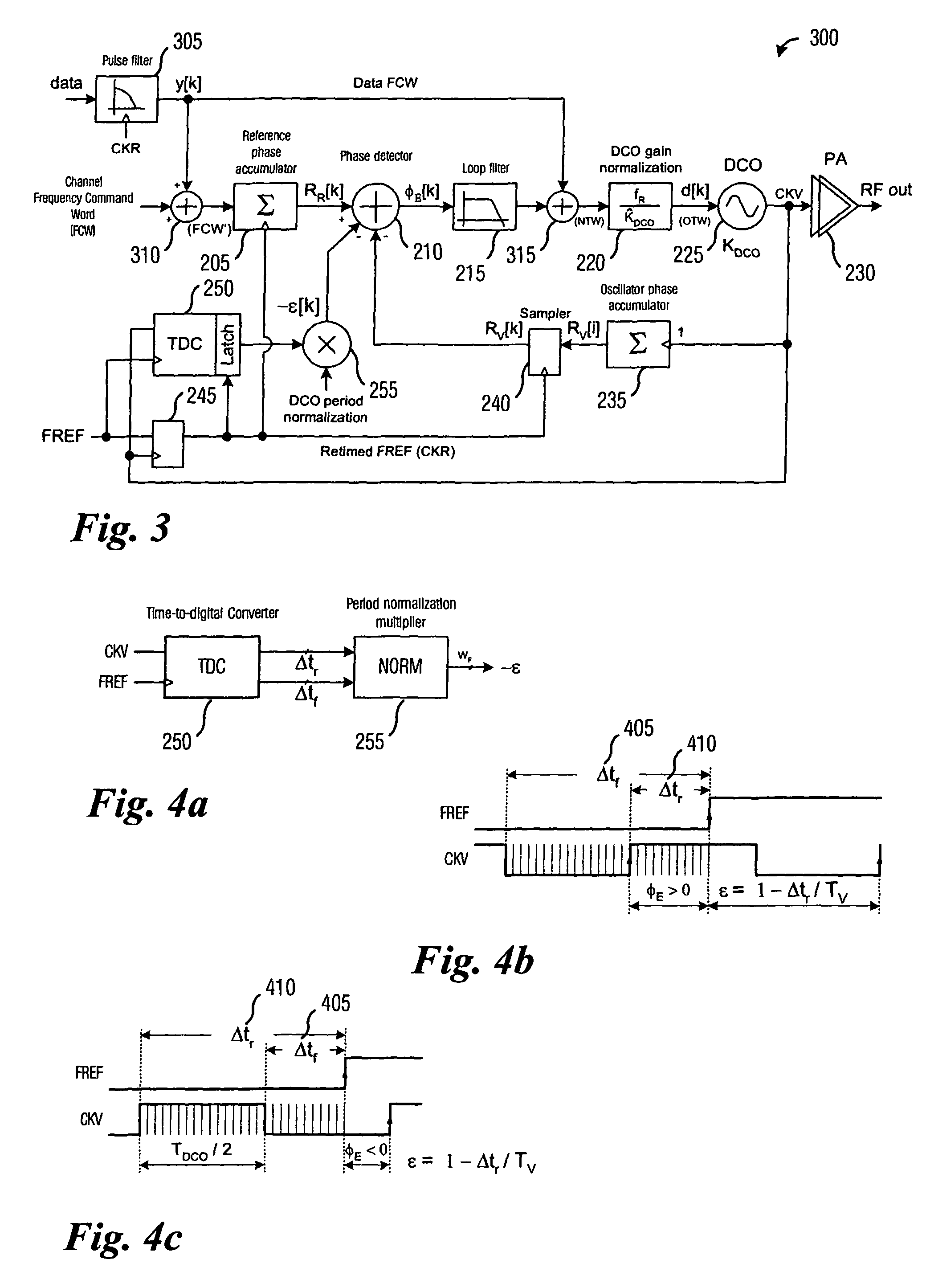
[0009]These and other problems are generally solved or circumvented, and technical advantages are generally achieved, by preferred embodiments of the present invention which provides a system and method for low-cost performance and compliance testing of local oscillators and transmitters for wireless RF applications.
[0013]An advantage of a preferred embodiment of the present invention is that the testing of the local oscillator and transmitter can be performed in a built-in self-test manner by observing and manipulating relatively low frequency digital signals. This can be performed without the need for expensive laboratory test equipment.
[0014]A further advantage of a preferred embodiment of the present invention is that the testing can be performed at multiple stages of an IC's life cycle. The testing can be performed on the die using test probes, after packaging, on a circuit board during product manufacturing, and in a self-contained device in the field. This is a heretofore unavailable degree of flexibility in testing.

Problems solved by technology

However, a significant portion of an IC's overall cost can be due to production testing.
One disadvantage of the prior art is that the testing can require expensive and sophisticated test equipment.
The potentially large expense can reduce the total number of test equipment available, therefore the testing can be a bottleneck in the production of the ICs.
A second disadvantage of the prior art is that the testing cannot be performed until after the ICs have been packaged.
This can be expensive, since the packaging can represent a large percentage of the cost of the IC.
Alternatively, the IC may need to be removed from its package, but this can be difficult and time intensive.
A third disadvantage of the prior art is that the testing cannot usually be performed once the packaged IC leaves the factory.
Therefore, testing in the field cannot be done to help diagnose performance issues that may arise during actual use, which may not be reproducible in the factory.

Method used


Image

  • Radio frequency built-in self test for quality monitoring of local oscillator and transmitter
  • Radio frequency built-in self test for quality monitoring of local oscillator and transmitter
  • Radio frequency built-in self test for quality monitoring of local oscillator and transmitter

Examples


Embodiment Construction

[0027]The making and using of the presently preferred embodiments are discussed in detail below. It should be appreciated, however, that the present invention provides many applicable inventive concepts that can be embodied in a wide variety of specific contexts. The specific embodiments discussed are merely illustrative of specific ways to make and use the invention, and do not limit the scope of the invention.

[0028]The present invention will be described with respect to preferred embodiments in a specific context, namely an all-digital PLL (ADPLL)-based integrated radio that is adherent to the Bluetooth technical standard. The Bluetooth technical standard is specified in a document entitled “Specification Volume 1: Specification of the Bluetooth System, Core,” version 1.1, published Feb. 22, 2001, which document is herein incorporated by reference. The invention may also be applied, however, to other ADPLL-based or digitally-intensive integrated radios that make use of a local osc...


PUM


Abstract

A system and method for low-cost performance and compliance testing of local oscillators and transmitters for wireless RF applications. A preferred embodiment comprises observing a digital signal from within an RF circuit, manipulating the signal with digital signal processing techniques, and determining if the RF circuit passes a test based upon results from the manipulating. Since the signal is clocked at a much lower frequency than an RF output of the RF circuit and the manipulation is performed digitally, testing can be performed at different stages of the production cycle and expensive test equipment can be eliminated.

Description

[0001]This application claims the benefit of U.S. Provisional Application No. 60 / 441,080, filed on Jan. 17, 2003, entitled “Type-II All-Digital PLL in Deep-Submicron CMOS”, which application is hereby incorporated herein by reference.CROSS-REFERENCE TO RELATED APPLICATIONS[0002]This application is related to the following co-pending and commonly assigned patent applications: Ser. No. 09 / 728,180, filed Dec. 1, 2000, entitled “Digital PLL with Gear Shift,” Ser. No. 10 / 464,957, filed Jun. 19, 2003, entitled “Type-II All-Digital Phase-Locked Loop (PLL),” and Ser. No. 10 / 464,982, filed Jun. 19, 2003, entitled “Fine-Grained Gear-Shifting of a Digital Phase-Locked Loop (PLL)” which applications are hereby incorporated herein by reference.TECHNICAL FIELD[0003]The present invention relates generally to a system and method for digital wireless radio frequency (RF) applications, and more particularly to a system and method for low-cost performance and compliance testing of local oscillators an...

Claims


Application Information

Patent Timeline
IPC IPC(8): H03D3/24G01R31/28G01R31/3187H03L7/085H03L7/095H04B17/00
CPCG01R31/2822G01R31/3187H04B17/19H03L7/095G01R31/2824H03L2207/50H03L7/085
Inventor STASZEWSKI, ROBERT B.LEIPOLD, DIRKDE-OBALDIA, ELIDA
Owner TEXAS INSTR INC
Learn More