
Adjustable circuit and RFID reader device

a reader device and adjustable circuit technology, applied in the direction of subscriber station connection selection arrangement, transmission, indirect connection of subscriber station, etc., can solve the problems of invariant frequency range of compensation, interference with weak tag response, and sensitivity of crosstalk to environmental influences in the vicinity of the system or the tag, so as to achieve inexpensive means , the effect of efficient suppression of carrier signal

Inactive Publication Date: 2012-10-09
PEPPERL FUCHS GMBH
View PDF5 Cites 10 Cited by
  • Summary
  • Abstract
  • Description
  • Claims
  • Application Information

AI Technical Summary

Benefits of technology

The solution achieves efficient suppression of carrier signals, increasing the system dynamic and range of RFID systems by up to eightfold, while reducing noise power and bit error rates, and is more cost-effective and faster than digital signal processing methods.

Problems solved by technology

The disadvantage of this procedure resides in the sensitivity of the crosstalk to environmental influences in the vicinity of the system or the tag.
Such environmental influences are e.g. larger reflecting areas which lead to a high transmission factor between the transmission and the reception antenna, which may interfere with the weak tag response as a disturbing signal.
A disadvantage of this procedure initially lies in the invariant frequency range of the compensation whereby the application is restricted to a single frequency.
Furthermore, compensation may only be achieved to a small extent on account of the discrete values of the available components.
The disadvantage of a digital signal processing on the one hand is the higher requirement for capital expenditure both for the acquisition of hardware and for the development time required for software development as well as the respective costs incurred herein.
On the other hand the hardware requires quite some space and is, depending on the respective requirements to be fulfilled, considerably slower than an analogue circuit.

Method used


Image

  • Adjustable circuit and RFID reader device
  • Adjustable circuit and RFID reader device
  • Adjustable circuit and RFID reader device

Examples


Embodiment Construction

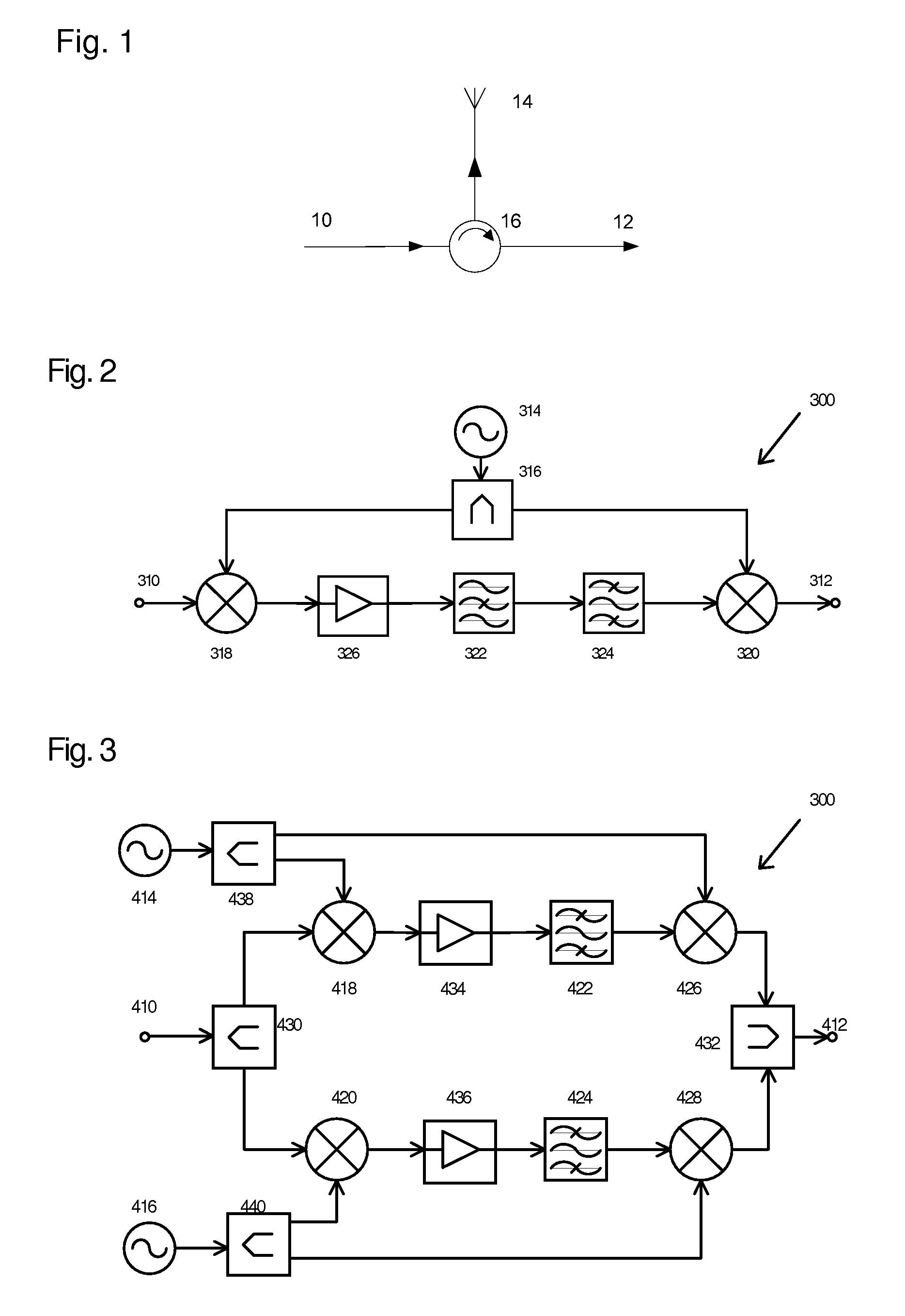
[0103]FIG. 1 shows a schematic illustration of a circuit in accordance with the state of the art for the realization of a transmission / receiving passage for a duplex operation required for a backscatter procedure, thereby using a circulator. The reader arrangement illustrated therein comprises a transmission connection 10, an antenna 14, a receiving connection 12 and a circulator 16 which is located between the transmission connection 10 and the receiving connection 12.

[0104]FIG. 2 shows an electrically adjustable circuit for filtering a transmission channel of an RFID signal with suppression of the carrier signal in the reception path between the input gate 310 and the output gate 312 comprising[0105]a. at least one oscillator 314 for generating a signal required for the mixing procedures,[0106]b. at least one power divider 316 for dividing the oscillator signal,[0107]c. at least two mixing stages 318 and 320, wherein the downconversion mixing stage 318 intermixes the input signal ...


PUM


Abstract

The present invention relates to an adjustable circuit for filtering a transmission channel of an RFID signal and for suppressing a carrier signal in the reception path between an input gate and an output gate, including at least one adjustable oscillator for generating an oscillator signal, at least one input mixing stage cooperating with the oscillator for mixing an input signal by means of the oscillator signal to an intermediate frequency and a blocking device arranged downstream of the input mixing stage or the input mixing stages for suppressing the carrier signal at the intermediate frequency.

Description

FIELD OF THE INVENTION[0001]The present invention relates in a first aspect to an adjustable circuit for the filtering of a transmission channel of an RFID signal and for the suppression of a carrier signal in the reception path between an input gate and an output gate. In a second aspect the invention relates to an RFID reader device with an inventive circuit.BACKGROUND OF THE INVENTION[0002]RFID-systems are employed in various fields of automatic identification. Especially in the field of industrial automation the use of RFID-systems proves to be of advantage. The growing requirements of quality management and quality assurance in automatic production can easily be realized with RFID-systems. In the production process production and measurement data can easily be stored on the object itself and taken alongside. In this way the data are available and can be documented on each object at any time. This also allows for a greater flexibility in production. Production parameters can be ...

Claims


Application Information

Patent Timeline
Patent Type & Authority Patents(United States)
IPC IPC(8): H04B7/00
CPCG06K7/10009H04B1/525G01S7/038H04B5/0062H04B5/77
Inventor SADEGHFAM, ARASHHEUERMANN, HOLGER
Owner PEPPERL FUCHS GMBH
Learn More